Plating apparatus and plating method

a technology of plating apparatus and plating method, which is applied in the direction of transportation and packaging, liquid/solution decomposition chemical coating, coating, etc., can solve the problems of difficult to generate a uniform downward air flow, the process bath presents an obstacle to the formation of downward air flow, and the particle suspension in the clean room cannot be fully removed. , to achieve the effect of not lowering the throughpu

Active Publication Date: 2016-07-12
EBARA CORP
View PDF3 Cites 1 Cited by
  • Summary
  • Abstract
  • Description
  • Claims
  • Application Information

AI Technical Summary

Benefits of technology

[0010]A second object is to provide a plating apparatus and a plating method which are capable of removing a processing liquid remaining on a substrate without causing a reduction in a throughput.
[0018]Furthermore, while the substrate holder is being transported in the horizontal direction, the suction mechanism can suck the processing liquid that remains on the substrate. Therefore, the processing liquid on the substrate can be removed without lowering the throughput.

Problems solved by technology

However, in the dip electroplating process, since a processing bath exists below the substrate that is being transported, the processing bath presents an obstacle to the formation of the downward air flow.
Hence it is difficult to generate a uniform downward air flow.
Therefore, particles that are suspended in the air in the clean room cannot fully be removed, and as a result the particles are liable to be attached to the surface of the substrate.
If the substrate holder is transported with the processing liquid remaining thereon, the processing liquid may drop from the substrate holder, thus possibly causing contamination.
Moreover, if the substrate holder, with the processing liquid remaining thereon, is moved to a subsequent processing bath, the processing liquid remaining on the substrate holder is mixed into a different processing liquid in the subsequent processing bath, adversely affecting the processing of the substrate in the subsequent processing bath.
However, these approaches are liable to increase a takt time of the plating apparatus and as a result reduce a throughput.

Method used


Image

  • Plating apparatus and plating method
  • Plating apparatus and plating method
  • Plating apparatus and plating method

Examples


Embodiment Construction

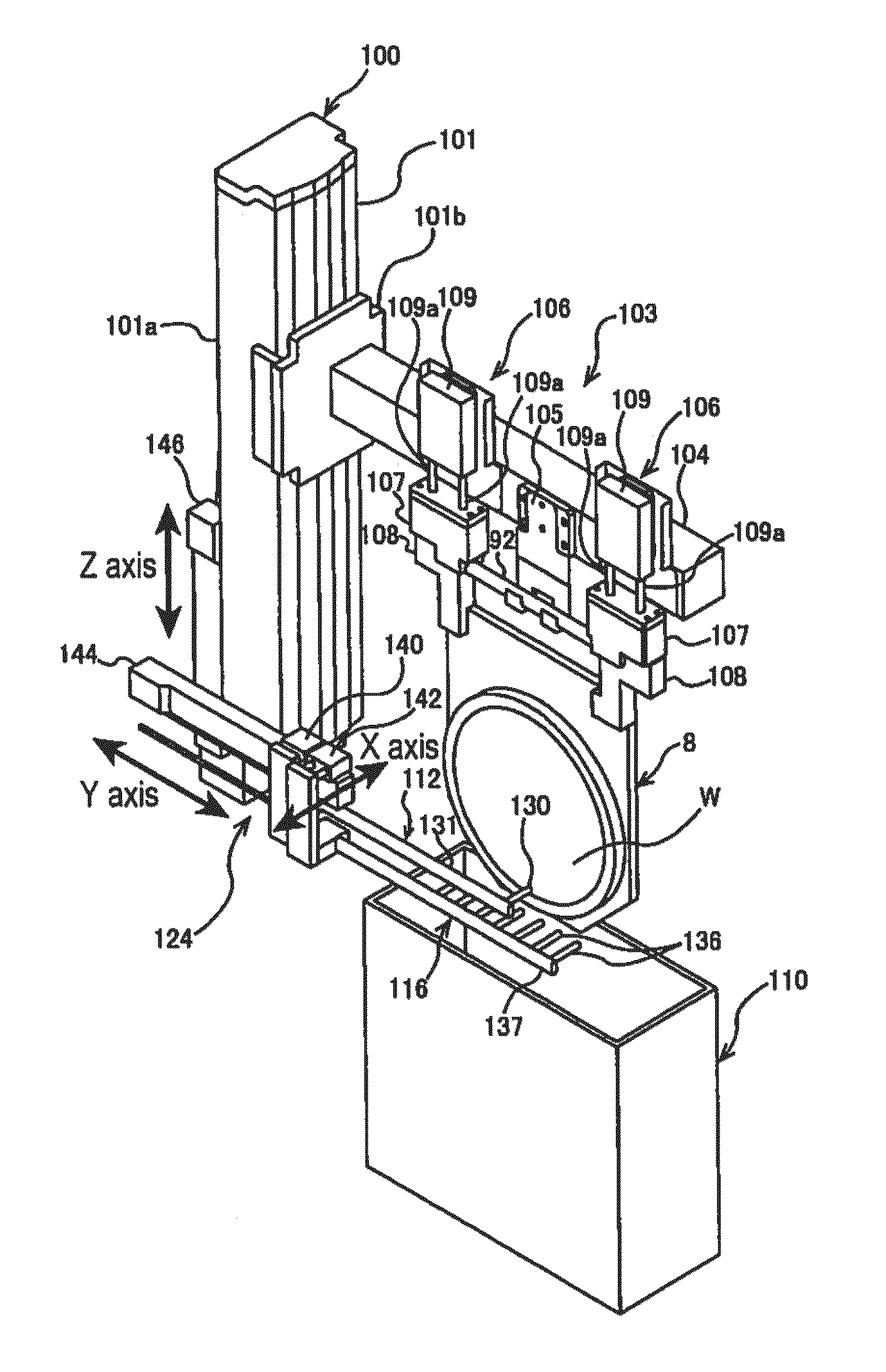
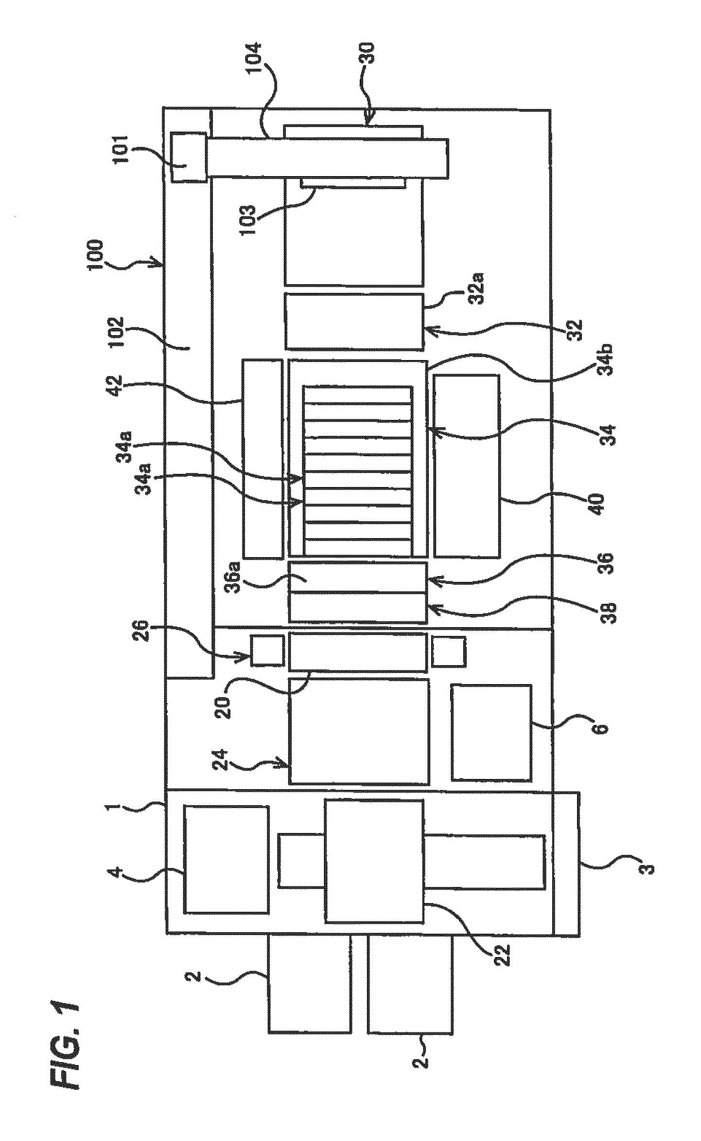
[0066]Embodiments will now be described in detail with reference to the drawings. Identical or corresponding elements are denoted by the same reference numerals and duplicate descriptions thereof are omitted. FIG. 1 shows an overall layout plan view of a plating apparatus according to an embodiment. As shown in FIG. 1, the plating apparatus includes a frame 1, two load ports 2 each receiving thereon a cassette in which substrates, such as wafers, are stored, and a controller 3 configured to control operations of the plating apparatus. In the frame 1, there are disposed an aligner 4 for aligning an orientation flat or a notch of a substrate with a predetermined direction, a spin-rinse drier (SRD) 6 for rotating a plated substrate at a high speed to dry the substrate, and a table 20 on which a substrate holder 8 (see FIG. 2 through FIG. 5) is placed in a horizontal position. Further, a substrate transfer robot 22 is provided for transporting the substrate between these units. The alig...


PUM

PropertyMeasurementUnit
diameteraaaaaaaaaa
diameteraaaaaaaaaa
distanceaaaaaaaaaa

Abstract

A plating apparatus includes a processing bath configured to store a processing liquid therein, a transporter configured to immerse a substrate holder, holding a substrate, in the processing liquid, raise the substrate holder out of the processing bath, and transport the substrate holder in a horizontal direction, and a gas flow generator configured to generate a clean gas flow forward of the substrate with respect to a direction in which the substrate holder is transported. The transporter moves the gas flow generator together with the substrate holder in the horizontal direction while transporting the substrate holder in the horizontal direction.

Description

CROSS REFERENCE TO RELATED APPLICATIONS[0001]This document claims priorities to Japanese Patent Application Number 2013-063800 filed Mar. 26, 2013 and Japanese Patent Application Number 2013-069729 filed Mar. 28, 2013, the entire contents of which are hereby incorporated by reference.BACKGROUND[0002]It is a common practice in TAB (tape automated bonding) or flip chip to form protruding connection electrodes (i.e., bumps) of gold, copper, solder or nickel, or of multiple layers of such metals at predetermined portions (electrodes) of a surface of a semiconductor chip having interconnects formed therein so that the semiconductor chip can be electrically coupled via the bumps to substrate electrodes or TAB electrodes. There are various methods usable for forming the bumps, such as electroplating, vapor deposition, printing, and ball bumping. In recent years, electroplating, which can form fine bumps and can be performed in a relatively stable manner, has been widely used, as the number...

Claims


Application Information

Patent Timeline
Patent Type & Authority Patents(United States)
IPC IPC(8): B65G45/26B65G45/22C25D17/00B65G45/24C23C18/16C25D17/06B65G45/10
CPCC25D17/06B65G45/10B65G45/22B65G45/24B65G45/26C23C18/163C23C18/1628C23C18/1632C23C18/1675C25D17/001C23C18/1689C25D5/48C25D21/02C25D21/04C25D21/06
Inventor HIRAO, TOMONORI
Owner EBARA CORP
Why Eureka
Try Eureka