Position determination in a lithography system using a substrate having a partially reflective position mark

a position mark and substrate technology, applied in the field of substrate and position determination in a lithography system, can solve the problems of increasing the cost of the system, system is sensitive to slight errors in the focus of light beam or tilt of the substrate, intensity signal does not closely resemble a sinusoid, etc., to achieve easy fabrication, high accuracy, and easy production

Active Publication Date: 2016-07-19
ASML NETHERLANDS BV
View PDF133 Cites 6 Cited by
  • Summary
  • Abstract
  • Description
  • Claims
  • Application Information

AI Technical Summary

Benefits of technology

[0011]In an embodiment the structures are aligned on points which are equidistantly spaced along the longitudinal direction. For instance, the structures may be aligned with their left most edge on such an equidistant point. At least some of these equidistantly spaced points may be free of a corresponding structure. Thus a substrate may be provided having a number of consecutive structures at a pitch c which pitch c is equal to the distance between the equidistanced points, and wherein a further structure is at a different pitch from its neighboring structure which is an integer multiple of said pitch c. This embodiment allows further variation in position of the structures. Preferably, the substrate is adapted to be used with a light beam projected onto said substrate, said light beam having a cross-sectional diameter which is larger that a distance between two neighboring of said equidistant points.
[0039]In an embodiment the pitch between neighboring structures along the longitudinal direction follows a sinusoid function of the position of said structures along the longitudinal direction. The structures are thus arranged for smoothly varying the reflection coefficient of the position mark along the longitudinal direction.

Problems solved by technology

A disadvantage of determining a position using light reflected in several diffraction orders is that the light detectors for the different diffraction orders have to be accurately positioned in the system, thus increasing the cost of the system.
Moreover, such systems are sensitive to slight errors in focus of the light beam or tilt of a substrate in relative to the light beam.
However, in practice the intensity distribution of the beam spot generally does not correspond to a homogeneous and sharply cut-off disc-like profile but instead follows a Gaussian profile, the resulting reflected intensity signal does not closely resemble a sinusoid function as a function of the position of the beam on the substrate.
As a result, the determination of the position of the beam spot on the substrate based on the intensity of the reflected beam is less accurate.

Method used


Image

  • Position determination in a lithography system using a substrate having a partially reflective position mark
  • Position determination in a lithography system using a substrate having a partially reflective position mark
  • Position determination in a lithography system using a substrate having a partially reflective position mark

Examples


Embodiment Construction

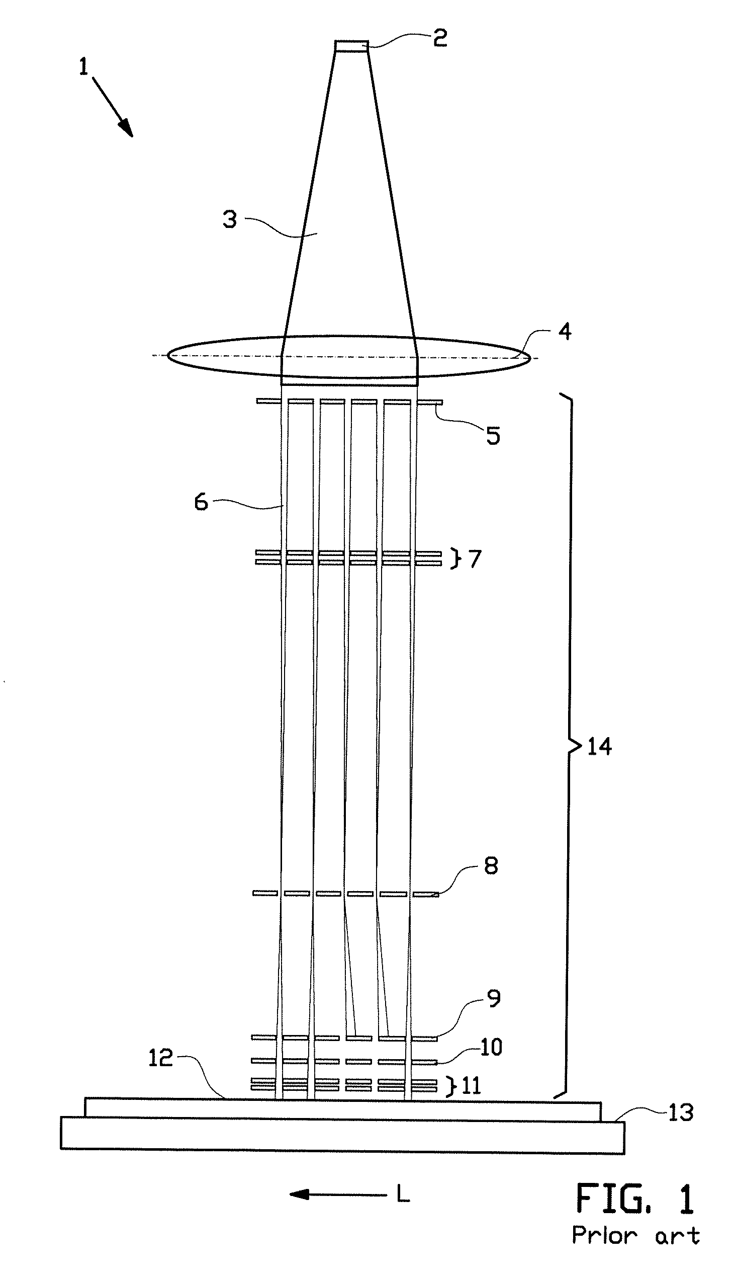
[0050]A known lithography system is shown in FIG. 1. The lithography system 1 comprises a charged particle beam source 2 which emits a charged particle beam 3. Charged particle beam 3 traverses a collimator 4 before impinging on an aperture array 5. The aperture array splits the beam into a multitude of charged particle beamlets 6 which are condensed by condenser array 7. At beam blanker array 8 individual beamlets may be blanked, i.e. may be individually deflected such that they encounter beam stop array 9 later on in their trajectories instead of passing through apertures in beam stop array 9. The beamlets that have not been blanked then pass through a scanning deflector 10 which is adapted to provide a scanning deflection of said beamlets. At the end of their trajectories the beamlets that have not been blanked pass through a focusing lens array 11 adapted for focusing said beamlets onto a surface of a target 12, for instance a wafer. The target is placed on a moveable target car...


PUM

PropertyMeasurementUnit
distanceaaaaaaaaaa
distanceaaaaaaaaaa
distanceaaaaaaaaaa

Abstract

The invention relates to a substrate for use in a lithography system, said substrate being provided with an at least partially reflective position mark comprising an array of structures, the array extending along a longitudinal direction of the mark, characterized in that said structures are arranged for varying a reflection coefficient of the mark along the longitudinal direction, wherein said reflection coefficient is determined for a predetermined wavelength. In an embodiment a specular reflection coefficient varies along the substrate, wherein high order diffractions are substantially absorbed by the substrate. A position of a beam on a substrate can thus be determined based on the intensity of its reflection in the substrate. The invention further relates to a positioning device and lithography system for cooperation with the substrate, and a method of manufacture of the substrate.

Description

[0001]This is a non-provisional application claiming the benefit of U.S. Provisional Application No. 61 / 478,126, filed Apr. 22, 2011, and U.S. Provisional Application No. 61 / 491,862, filed May 31, 2011.BACKGROUND[0002]The present invention relates to a substrate and method for position determination in a lithography system. In particular the invention relates to a substrate having provided thereon an at least partially reflective position mark comprising an array of structures, the array extending along a longitudinal direction of the mark, and a method for determining a position of such a substrate in a lithography system.[0003]Position determination in lithography systems is generally known, normally using detection of light reflected in several diffraction orders, as is described for instance in U.S. Pat. No. 4,967,088. A disadvantage of determining a position using light reflected in several diffraction orders is that the light detectors for the different diffraction orders have...

Claims


Application Information

Patent Timeline
Patent Type & Authority Patents(United States)
IPC IPC(8): G03F9/00
CPCG03F9/7088G03F9/7076H01J2237/30438H01J2237/31774H01J2237/2482G03F7/20G03F9/00
Inventor DE BOER, GUIDOVERGEER, NIELS
Owner ASML NETHERLANDS BV
Why Eureka
Try Eureka