Blocker of geomagnetically induced currents (GIC)

a geomagnetically induced current and blocker technology, applied in the direction of fault current, process and machine control, instruments, etc., can solve the problems of reducing gic, affecting the operation of the power capacitor, etc., to achieve the effect of simple, convenient installation, and reduced gi

Active Publication Date: 2016-07-19
RAMIREZ ALBERTO RAUL
View PDF8 Cites 4 Cited by
  • Summary
  • Abstract
  • Description
  • Claims
  • Application Information

AI Technical Summary

Benefits of technology

[0013]Said surge arrester avoids the requirement to have any other specific power equipment or elements such as capacitors, condensers and / or resistors, since it is exclusively committed to blocking Geomagnetically Induced Currents. Said surge arrester is preferably a metal oxide surge arrester. The herein disclosed invention provides a device that is simple, passive, size convenient, easy to install, highly cost-effective and energy efficient. Furthermore, its resistive components can be trouble-free switched on / off; it comprises only two standard distribution voltage components, implying a negligible layout change to the transformer substation.

Problems solved by technology

In general, it may cause wave distortion and equipment overheating.
The described phenomenon poses such a major threat to the electric power grid that it has captured attention at the highest levels of the US Federal Government.
First, the attainable reduction of GIC is relative and depends on the resistor rating, and therefore size and cost.
Moreover, resistor ratings are typically based on a 10-second deployment which poses a thermal concern if the deployment requires a time period longer than 10 seconds.
However, a real number of pitfalls can be associated to this approach; first and foremost, switching of power capacitors is well known to be quite problematic because of the huge transient currents these devices can cause compelling a need to discharge them after switching the unit off.
Secondly, a problem stemming from the fact that the capacitor is placed in series with the transformer Y winding, on its neutral / ground side, and therefore in series with the transformer's non-linear magnetizing reactance, thus posing a number of design challenges; notably because of the problematic proneness to ferroresonance i.e. a series LC resonant condition that can establish itself since resonant tuning is enhanced by the non-linear nature of the transformer reactance that can create, in combination with the capacitor, numerous series oscillatory natural frequencies.
Hence this problem requires installing yet a resonance damping resistor in that series circuit; but placing such a resistor brings also all the shortcomings discussed above for the case of the neutral grounding resistor approach and none of its advantages.
Thirdly, the presence of a capacitor may be problematic in case a power system ground fault occurs when this device is on, since the capacitor causes a transient DC offset on top of the AC fault current which impedes such current to go through a zero value, as the AC current wave does, complicating substantially the clearance of that AC fault by grid circuit breakers.
In addition, capacitor units placed at transformer neutrals may produce various additional well-known hazards such as neutral instability, voltage magnification and even neutral inversion phenomena.
In each case more components and functionalities must be incorporated to cope with these problems causing a major impact in cost, size and complexity.
In fact the resulting many components, with convoluted functionalities, make difficult to ponder the mitigation device potential failure modes and hence making difficult to arrive at a reasonable failure rate, essential for the power system reliability impact it will cause after installation at a very sensitive power system point.
All these reasons have caused the electric utility industry to be reluctant to adopt this technology, with the end result there is to date not a single installation in the US despite the urgency to protect the electric grid from these serious threats.

Method used


Image

  • Blocker of geomagnetically induced currents (GIC)
  • Blocker of geomagnetically induced currents (GIC)
  • Blocker of geomagnetically induced currents (GIC)

Examples


Embodiment Construction

[0019]The following detailed description illustrates the invention by way of example and is not limited to the particular limitations presented herein as principles of the invention. This description is directed to enable one skilled in the art to make and use the invention by describing embodiments, adaptations, variations and alternatives of the invention. Potential variations of the limitations herein described are within the scope of the invention. Particularly, the size and shapes of the invention's elements illustrated in the discussion may be varied and still provide embodiments having different sizes or geometric shapes, that are within the scope of the instant invention.

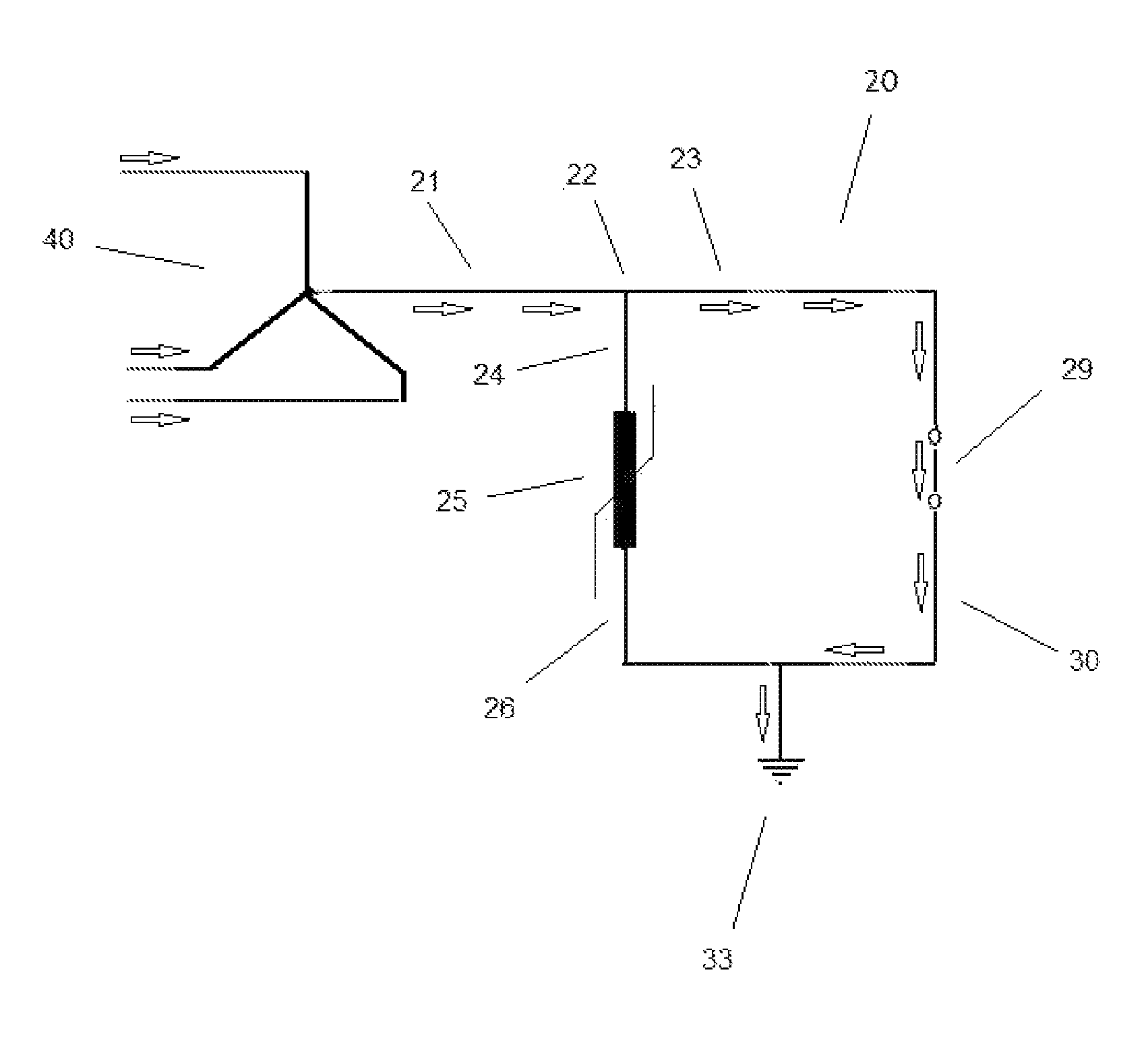
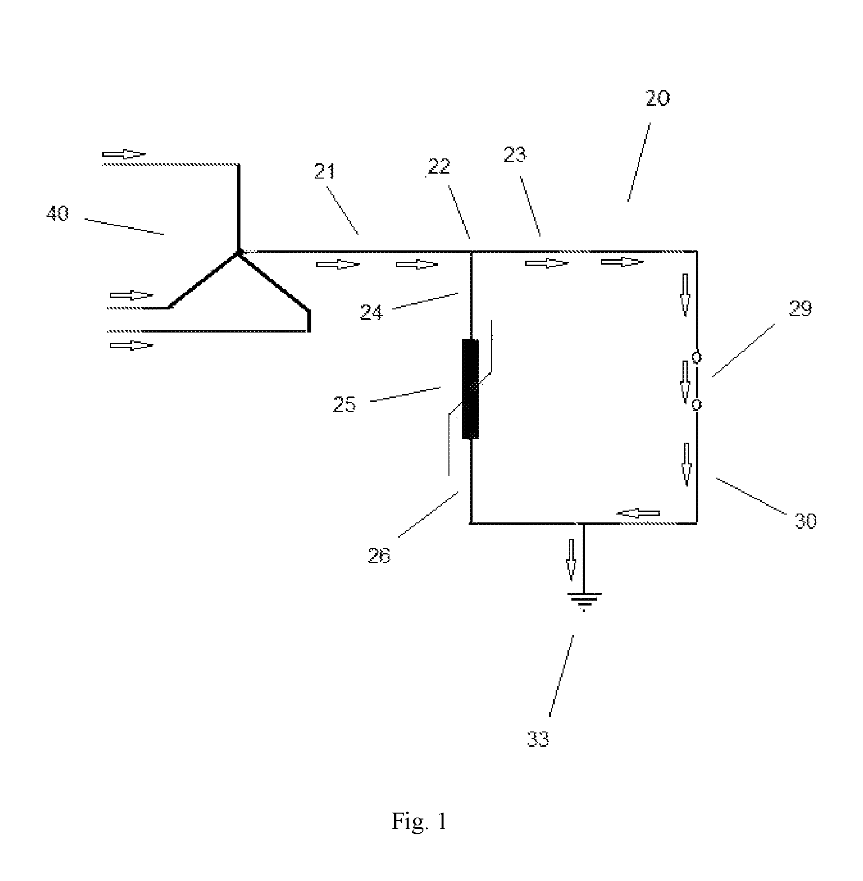
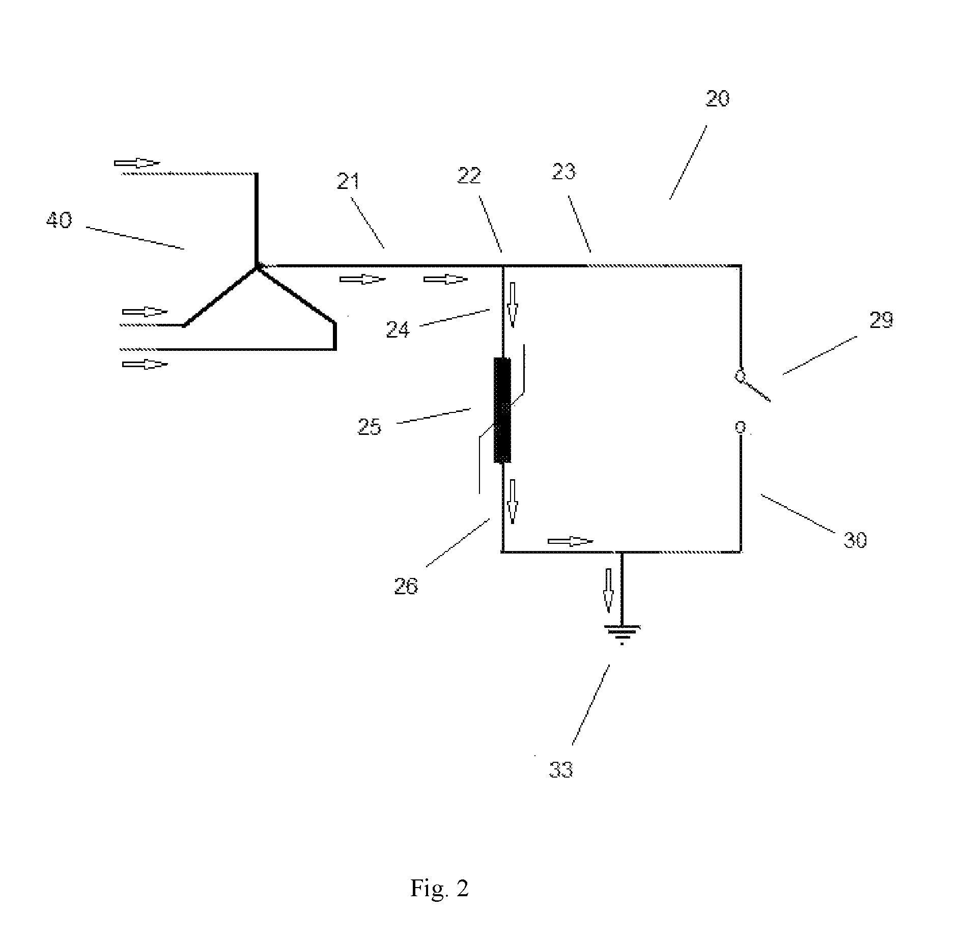
[0020]In general terms, the instant disclosure describes a device for protecting power transformers from the deleterious flow GIC or DC currents directly or indirectly caused by Geomagnetic Disturbances, originated by either solar winds or intended electromagnetic pulses EMP. The preferred embodiments of thi...


PUM

PropertyMeasurementUnit
timeaaaaaaaaaa
applied voltageaaaaaaaaaa
currentaaaaaaaaaa

Abstract

A device for mitigation Geomagnetic Induce Currents in the power distribution network is described. It may be connected to the neutral of a star-connected three-phase transformer of the power distribution system to ground without compromising its basic insulation, operation or integrity of the system. It requires a circuit having a surge arrester resistor having an adaptive nonlinear negative volt-ampere which is inserted from the transformer neutral to ground and a ground switch connected to the ground and also connected to the surge arrester.The device has two different current paths: whenever there is no GIC the switch remains closed and current flows from the transformer to the ground via the ground switch. Under Geomagnetic Induce Currents, the ground switch opens, allowing the induced current to flow from the transformer to the ground via the surge arrester. The device is formulated and designed according to IEEE / ANSI / NEMA recommended insulation coordination guidelines in order to sustain proper protective margins to the equipment neutral basic insulation levels (BIL, BSL).

Description

TECHNICAL FIELD[0001]This invention is directed to a device useful in mitigating the Geomagnetically Induced Currents (GIC) in a transformer apparatus of an AC power distribution network in order to avoid the potential damage caused by such currents.BACKGROUND[0002]In its most common form, Geomagnetic Induced Currents (GIC) is a well-known phenomenon that takes place as a consequence of Geomagnetic Disturbances (GMD), caused by either solar winds or intended electromagnetic pulses EMP. These shock waves can interact with the conductors of transmission and distribution circuits; such interaction causes, according to the laws of physics, the induction of currents in these circuits. Once the GIC flows in the network, it reaches the power transformers as well as the instrument transformers, shunt reactors and phase shifters connected to the transmission lines, entering through their phase connections and returning from their earthed neutral. The most important effects are related to the...

Claims


Application Information

Patent Timeline
Patent Type & Authority Patents(United States)
IPC IPC(8): H01F27/34H02H3/16G05F3/04H02H9/08
CPCH01F27/34G05F3/04H02H3/165H02H9/08
Inventor RAMIREZ, ALBERTO RAUL
Owner RAMIREZ ALBERTO RAUL
Why Eureka
Try Eureka