Geometry calibration algorithm for large flat module detector CT scanner

a technology of ct scanner and geometric calibration algorithm, which is applied in the field of geometric calibration of ct scanner, can solve the problems of affecting the size of air gaps between adjacent modules, stochastic errors will be introduced in the size of air gaps, and the coherence between the actual size of air gaps and the designed size of them cannot be guaranteed, so as to achieve accurate geometric parameters, low cost, and easy implementation

Active Publication Date: 2016-07-26
GE MEDICAL SYST GLOBAL TECH CO LLC
View PDF12 Cites 147 Cited by
  • Summary
  • Abstract
  • Description
  • Claims
  • Application Information

AI Technical Summary

Benefits of technology

[0009]In order to solve the above mentioned problem, the present disclosure provides a simple and effective method and apparatus for geometric calibration of a CT scanner including a large flat module detector, whereby accurate sizes of air gaps between adjacent modules, an accurate ISO channel, and an improved MTF can be obtained.
[0031]The method and apparatus provided by the present disclosure can accurately obtain the immeasurable geometric parameters for a CT scanner with a large flat module detector. Embodiments of the present invention ensure the feasibility of applying a low cost large flat module detector into a CT scanner. Embodiments of the present invention are easy to implement, the calibration phantom is very simple, the scan protocol is an ordinary axial scan, and the calculation is fast. Furthermore, the present invention can accurately acquire the sizes of air gaps between adjacent modules and the ISO channel, such that artifacts induced by inaccurate sizes of air gaps between adjacent modules and the inaccurate ISO channel can be completely eliminated, and the MTF improved.

Problems solved by technology

Due to the actual manufacture and installation techniques of detectors, coherence between the actual sizes of these air gaps and the designed size thereof can hardly be guaranteed.
However, since the modules in the detector are typically installed obliquely at a certain angle relative to each other, stochastic errors will be introduced in the sizes of air gaps between adjacent modules, such that the sizes of air gaps between adjacent modules may be different in the same detector, and among different systems.
Furthermore, for a large flat module detector, obliquely incident X-ray photons may affect the effective response positions of the detector cells at the module edges, such that the effective response positions thereof are not at the centers of the detector cells, thereby affecting the sizes of air gaps between adjacent modules.
Any mismatch between data acquisition and image reconstruction resulting from incoherence between the actual sizes of air gaps between adjacent modules and the designed size thereof may lead to severe ring artifacts in the reconstructed images.
When the errors introduced for the size of air gaps between adjacent modules are greater than ±0.04 mm, ring artifacts will occur in the reconstructed images, which is undesirable.
On the other hand, after the detector is secured to the gantry, its position cannot be adjusted.
However, considering the precision of the mounting, the position of the detector may not correspond exactly to the desired position, which will affect the ISO channel.
In other words, the actual ISO channel may not be the desired ISO channel.
More seriously, double shadow artifacts may appear in the reconstructed images.

Method used


Image

  • Geometry calibration algorithm for large flat module detector CT scanner
  • Geometry calibration algorithm for large flat module detector CT scanner
  • Geometry calibration algorithm for large flat module detector CT scanner

Examples


Embodiment Construction

[0043]Embodiments of the invention described herein are illustrated by way of example and not by way of limitation in the accompanying figures. For simplicity and clarity of illustration, elements illustrated in the figures are not necessarily drawn to scale. For example, the dimensions of some elements may be exaggerated relative to other elements for clarity. Further, where considered appropriate, reference numerals have been repeated among the figures to indicate corresponding or analogous elements. Reference in the specification to “one embodiment” or “an embodiment” of the invention means that a particular feature, structure, or characteristic described in connection with the embodiment is included in at least one embodiment of the invention. Thus, the appearances of the phrase “in one embodiment” in various places throughout the specification are not necessarily all referring to the same embodiment.

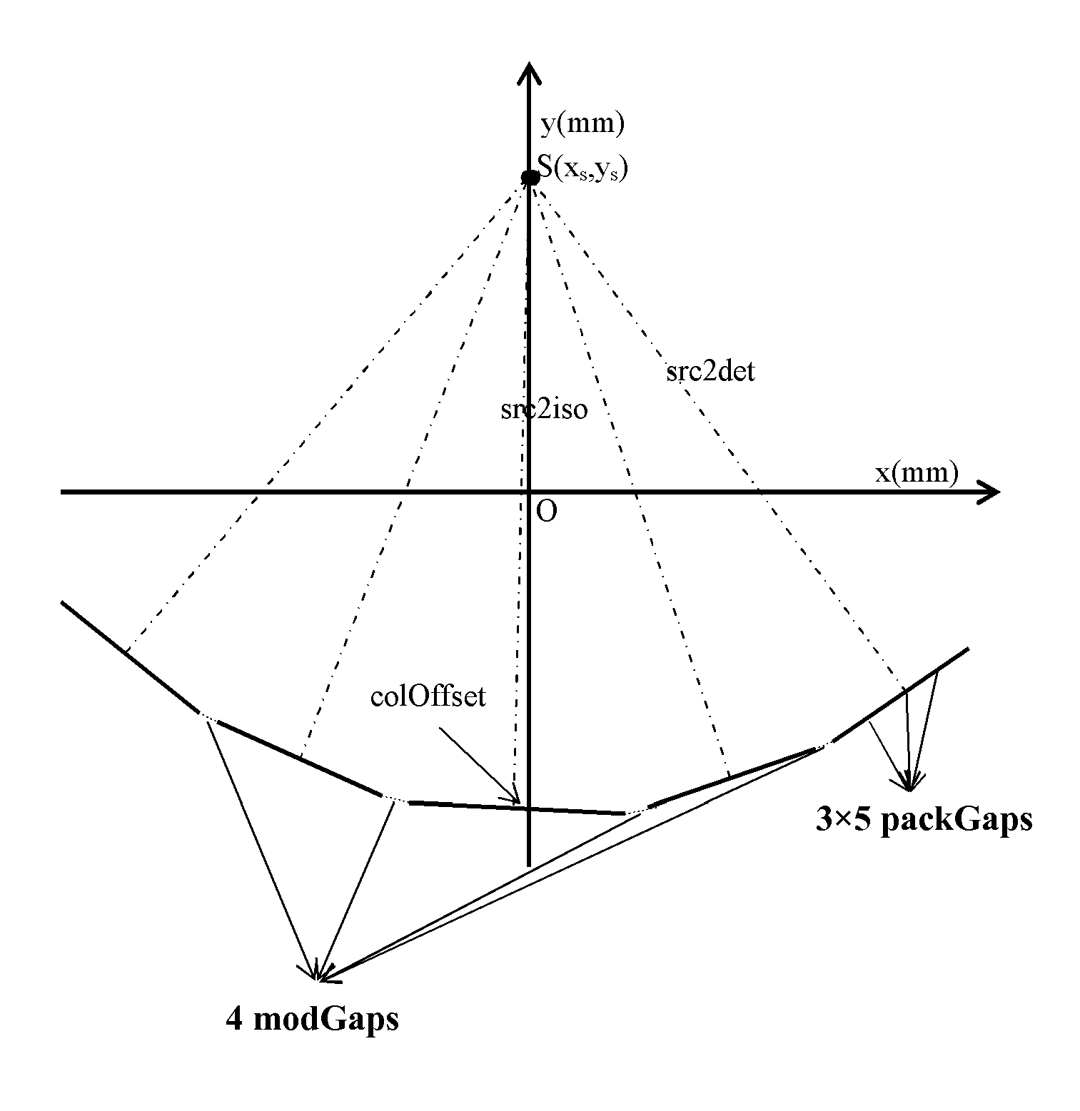
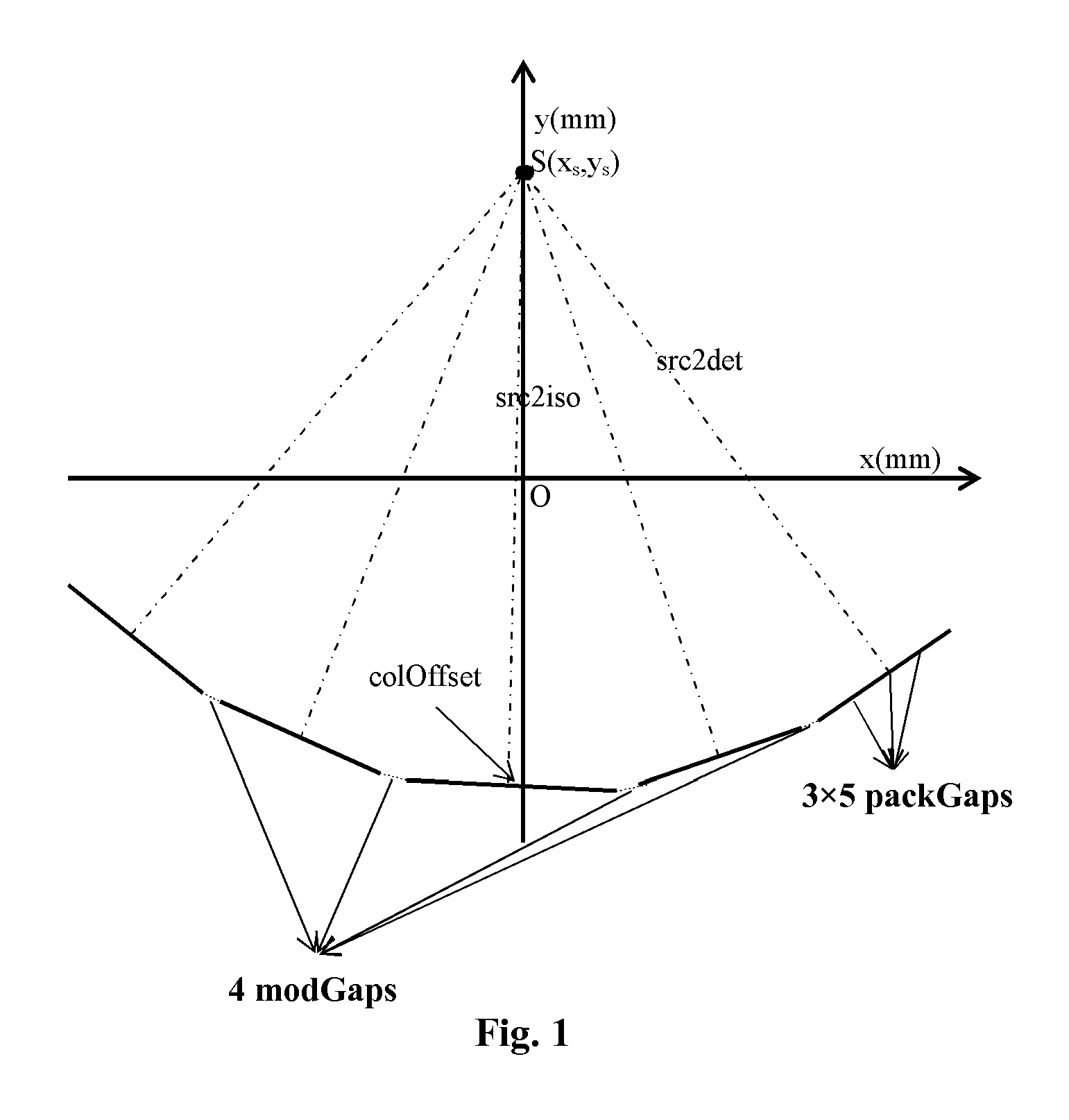
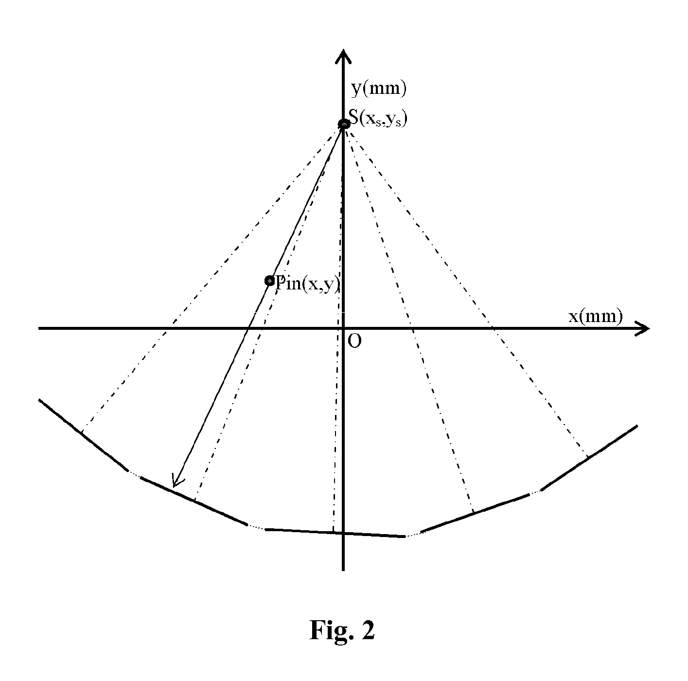
[0044]The present invention acquires accurate geometric parameters of a CT scan...


PUM


Abstract

A method for geometric calibration of a CT scanner, including, for each row of at least one row of detector cells, establishing a complete geometric description of the CT scanner, including at least one unknown geometric parameter, establishing a description of a forward projection function using the complete geometric description, acquiring actual projection coordinates of a calibration phantom placed in a scanning field of view (SFOV) on a current row of detector cells and corresponding to a plurality of angles, acquiring calculated projection coordinates of the calibration phantom on the current row of detector cells and corresponding to the plurality of angles using the description of the forward projection function, and acquiring a calibrated value for the at least one unknown geometric parameter by evaluating the at least one unknown geometric parameter based on the acquired actual projection coordinates and calculated projection coordinates via a nonlinear least square fitting algorithm.

Description

TECHNICAL FIELD[0001]The present disclosure relates to the field of computer tomography (CT), and in particular, to a method and an apparatus for geometric calibration of a CT scanner.BACKGROUND ART[0002]To save on the cost of detectors in a CT scanner, a large flat module detector has been introduced in the CT scanner. This large flat module detector has a plurality of flat modules, each module having a plurality of packs, each pack having a plurality of conventional detector cells. Compared to the traditional 3rd generation curved detector architecture, this large flat module detector is much larger, and is also different in many other ways. For example, in a large flat module detector, there exist air gaps between adjacent modules and between adjacent packs, while the traditional 3rd generation curved detector architecture contains no such air gaps.[0003]Due to the actual manufacture and installation techniques of detectors, coherence between the actual sizes of these air gaps an...

Claims


Application Information

Patent Timeline
Patent Type & Authority Patents(United States)
IPC IPC(8): A61B6/03A61B6/00
CPCA61B6/585A61B6/032A61B6/583
Inventor DONG, JIAQINLI, SHUOLI, JUNCAO, XIMIAOWANG, BIN
Owner GE MEDICAL SYST GLOBAL TECH CO LLC
Why Eureka
Try Eureka