Laser cutting method optimized in terms of mass defect per unit length

a laser cutting method and laser cutting technology, applied in laser beam welding apparatus, nuclear engineering, facility decommissioning, etc., can solve the problems of no laser cutting method optimized, difficult collection of slag, and even more undesirable sedimentation slag

Active Publication Date: 2016-07-26
COMMISSARIAT A LENERGIE ATOMIQUE ET AUX ENERGIES ALTERNATIVES
View PDF3 Cites 0 Cited by
  • Summary
  • Abstract
  • Description
  • Claims
  • Application Information

AI Technical Summary

Benefits of technology

[0022]with the type of system,in order to minimize the mass defect per unit length of the piece during cutting of said piece,
[0037]It makes it possible indeed to favour formation of adherent slag, instead of sedimented slag, to facilitate the evacuation of the cutting residues with the cut-out material.
[0038]The dispersion of the sedimented slag in the surrounding environment is reduced.
[0042]It will be understood however that by minimising the mass defect per unit length, the proportion of adherent slag is increased compared to sedimented slag.
[0043]The reduction particularly of sedimented slag is advantageous in the case where laser cutting is used for dismantling nuclear facilities. The collection of wastes is thereby facilitated.

Problems solved by technology

On the other hand, dispersion of sedimented slag makes the collection thereof difficult.
It will be easily understood that when laser cutting is used for dismantling nuclear facilities, sedimented slag is even more undesirable, because it contains irradiated or contaminated materials, which are consequently radioactive.
No optimized laser cutting method exists at the present time that makes it possible to limit the production of residues, particularly of sedimented slag.

Method used


Image

  • Laser cutting method optimized in terms of mass defect per unit length
  • Laser cutting method optimized in terms of mass defect per unit length
  • Laser cutting method optimized in terms of mass defect per unit length

Examples


Embodiment Construction

[0015]The invention proposes overcoming at least one of these drawbacks.

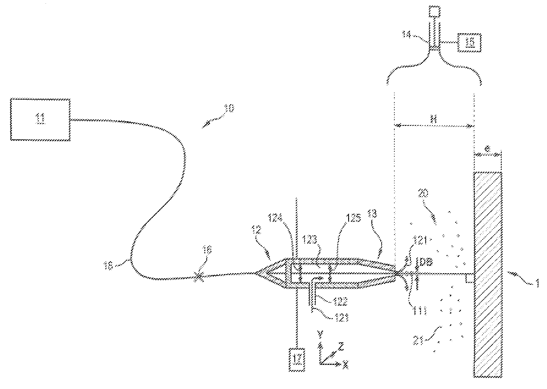
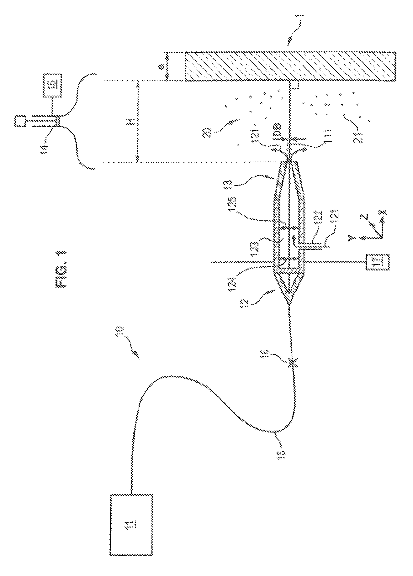
[0016]To this end, according to the invention an optimized laser cutting method for cutting out a piece from a material by a cutting system is proposed and comprises[0017]a laser source for producing a laser beam having a power, and[0018]a cutting head comprising an end nozzle for the passage of the cutting laser beam,

wherein the method is characterized in that it comprises a step of determining a cutting power Pd such that:

Pd=Max(Popt;λe)

where Max is the mathematical operator of the maximum,

[0019]Popt is an optimal power of the laser beam of the cutting system, determined in accordance[0020]with the piece to be cut out, and / or[0021]with cutting parameters and / or[0022]with the type of system,

in order to minimize the mass defect per unit length of the piece during cutting of said piece,

[0023]λ is a leading coefficient representing the number of kW required for cutting out the piece per mm of piece thickness, and

[...


PUM

PropertyMeasurementUnit
diametersaaaaaaaaaa
diametersaaaaaaaaaa
diameteraaaaaaaaaa

Abstract

The invention relates to an optimized laser cutting method for cutting a part from a material by means of a cutting system comprising: a laser source for producing a laser beam having a certain power; and a cutting head comprising an end nozzle for passage of a cutting laser beam, said method being characterized in that it comprises a step of determining the cutting power Pd such that: Pd=Max(Popt;λe) where Max is the mathematical operator of the maximum, Popt is an optimal power of the laser beam of the cutting system, which is predetermined in accordance with the part to be cut, and / or with cutting parameters and / or with system parameters, to minimize the mass defect per unit length of the part when the part is being cut, λ is a leading coefficient representing the number of kW required for cutting the part per mm of the thickness of the part, and e is the thickness of the part in mm.

Description

GENERAL TECHNICAL FIELD[0001]The present invention relates to an optimized laser cutting method for cutting a part from a material by means of a cutting system comprising[0002]a laser source for producing a laser beam having a certain power, and[0003]a cutting head comprising an end nozzle for the passage of the cutting laser beam.PRIOR ART[0004]An application of lasers for cutting materials, particularly metals, is known. The cutting is created by evaporation and melting of the material subjected to the laser beam.[0005]A laser cutting system comprises in a conventional manner a head, comprising an internal chamber and an inlet of gas under pressure and filling the chamber before being ejected towards the material to be cut.[0006]The gas makes it possible to evacuate the material that was melted and vaporized by the laser beam.[0007]The molten material, which is in part oxidized, re-solidifies outside of the cutting. The following may be distinguished:[0008]slag adhering to the sur...

Claims


Application Information

Patent Timeline
Patent Type & Authority Patents(United States)
IPC IPC(8): B23K26/36B23K26/06B23K26/38B23K26/14G21D1/00
CPCB23K26/38B23K26/0626B23K26/14G21D1/003
Inventor CHAGNOT, CHRISTOPHECANNEAU, GAETANPILOT, GUYFAUVEL, SYLVAIN
Owner COMMISSARIAT A LENERGIE ATOMIQUE ET AUX ENERGIES ALTERNATIVES
Why Eureka
Try Eureka