Dust extraction device for a rotary power tool

a technology of cutting tool and extraction device, which is applied in the direction of material removal/addition, maintenance and safety accessories, climate sustainability, etc., can solve the problems of excluding the implementation of standard power tools, high impact on gravity, and inherent power alteration, so as to increase the suction efficiency and enhance the vacuum force. , the effect of easy attachment to existing drilling elements

Inactive Publication Date: 2016-07-26
HAVIV LIOR
View PDF29 Cites 6 Cited by
  • Summary
  • Abstract
  • Description
  • Claims
  • Application Information

AI Technical Summary

Benefits of technology

[0020]The invention avoids the need to mount the impeller hub on the rear shank of the drill bit since it engages the drill bit in a manner that permits rotation of the hub as well as axial movement of the drill bit through the hub. Consequently, as the drill bit rotates, so too does the impeller thereby sucking in air and debris into the casing. But unlike the device disclosed in above-mentioned U.S. Pat. No. 5,772,367, the device according to the invention may move axially along the drill bit. Furthermore since the hub is able to rotate independent of the casing, the casing may be held manually close to, and typically in contact with, the work surface thus applying maximum suction without impeding the rotation of the impeller. The drill bit is then urged toward the work surface without requiring any movement of the casing. This is possibly because as the drill bit is advanced, it moves axially relative to the hub while the hub continues to rotate.
[0021]The impeller this acts as a fan like element that is clutched directly on the drill bit to be propelled and rotates concurrently with the drill bit. The extractor device casing, which encloses the fan element, is designed to be constrained of the fan rotational motion. In use, the device casing is preferably manually held by the operator. However, since it is stationary it could be fixed to the body of the power drill by a telescopic bracket or arm that allows the power drill and attached drill bit to be advanced toward the workpiece while maintaining the device casing in stationary contact with the workpiece. The relative rotational motion between the rotating fan element and the non-rotating casing generates an enhanced vacuum force for fluid flow through the device. In addition, the entire attachment (i.e. fan plus casing) is free to move linearly along the bit shaft independently of rotation of the bit and fan. This permits tight and full contact between the extraction element and the working plane prior to drilling and through the entire drilling process regardless of the bit penetration into the working plane.
[0022]Because the dust extractor is directly coupled to the rotation of the drilling element it is inherently active only when required. In addition, the close proximity of the device and its flow inlet opening to the work-surface during the entire drilling process increases the suction efficiency dramatically and eliminates the use of gap-compensating elements such as telescopic sleeves.
[0023]The resulting outcome of this design is a non-electrical power-free dust extracting device which is easily attached to existing drilling elements and requires no internal modifications for the drill in use.
[0024]The extractor device is compact, small, inexpensive, portable, green (no use of power), and versatile. It can be removed and applied easily on any drill bit of suitable gauge.

Problems solved by technology

The vibrations associated with the operation of a power drill and the rotation of the cutting tool tend to vigorously disperse these residues all around the working environment, forcing the user to clean and remove the scattered dust and residues.
However, they oblige a hermetically sealed boundary with the drilled zone and are highly affected by gravity (i.e. drilling orientation), especially when detaching the drill from the drilled zone.
Some of these devices compel an inherent alteration in the power-tool design and manufacture and thus exclude their implementation on existing, standard power-tools.
This limits the suction efficiency of the device since once air is sucked into the front end of the conical casing, there does not appear to be a mechanism that directs the air and debris toward the annular filter other than the centrifugal force of the rotating casing.
Also, since the entire attachment including the casing and the impellers rotates as a single unit, there is generated a large torque / moment which potentially can impose a risk for the operator.
Additionally, once the drill bit is rotating, the attachment cannot be handled so that the operator cannot change its location on the shaft of the tool bit.
Also since the casing is rotating, the attachment cannot be brought too close to the workpiece because it will frictionally swivel and scratch the workpiece surrounding surface.
Moreover, even when fully contracted the length of the casing extends along the cutting flute of the drill bit, which significantly reduces its effective length and limits the depth of penetration into the workpiece.
This “one size fits all” is clearly a limitation since it is hardly practicable that the resilient material will be capable of accommodating drill bits across the complete range of the chuck, typically from less than 1 mm to 13 mm.

Method used


Image

  • Dust extraction device for a rotary power tool
  • Dust extraction device for a rotary power tool
  • Dust extraction device for a rotary power tool

Examples


Embodiment Construction

[0033]In the following description of some embodiments, identical components that appear in more than one figure or that share similar functionality will be referenced by identical reference symbols.

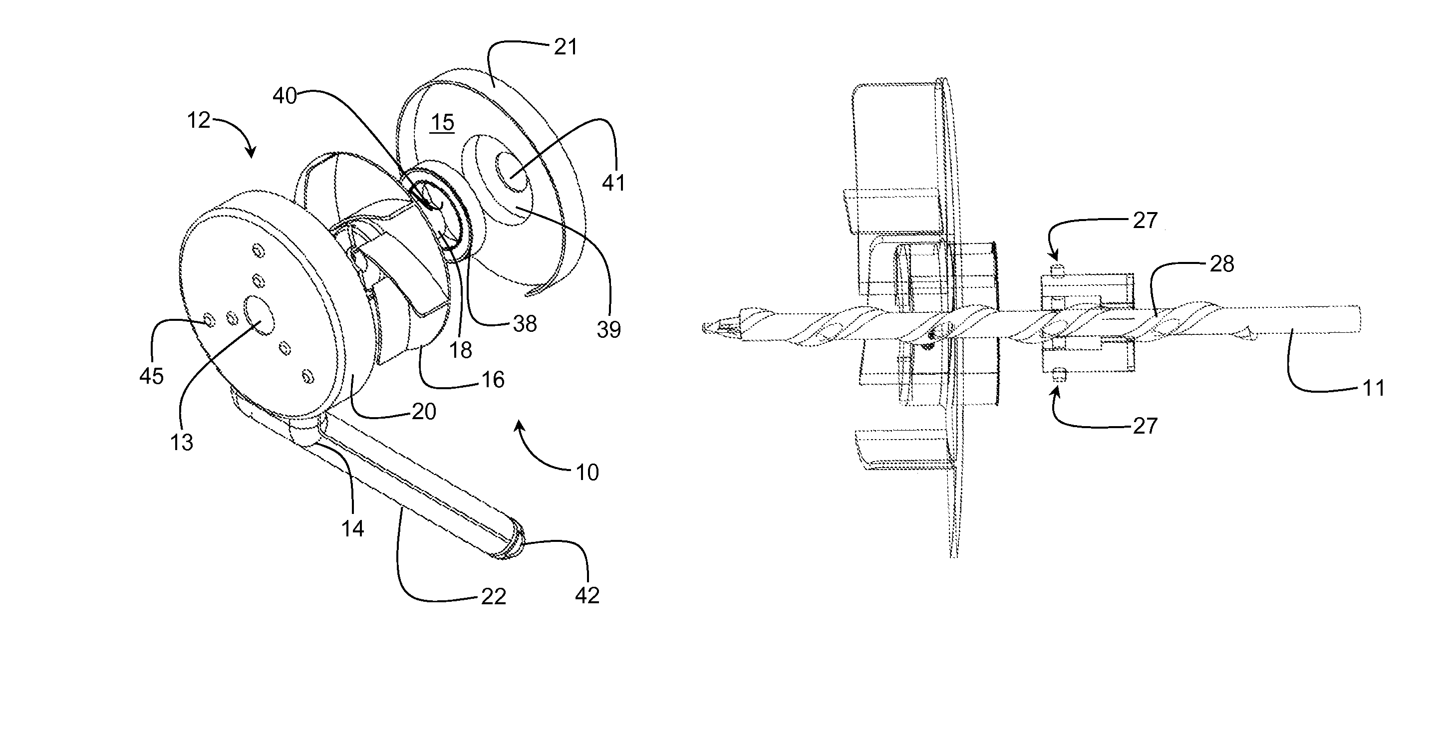
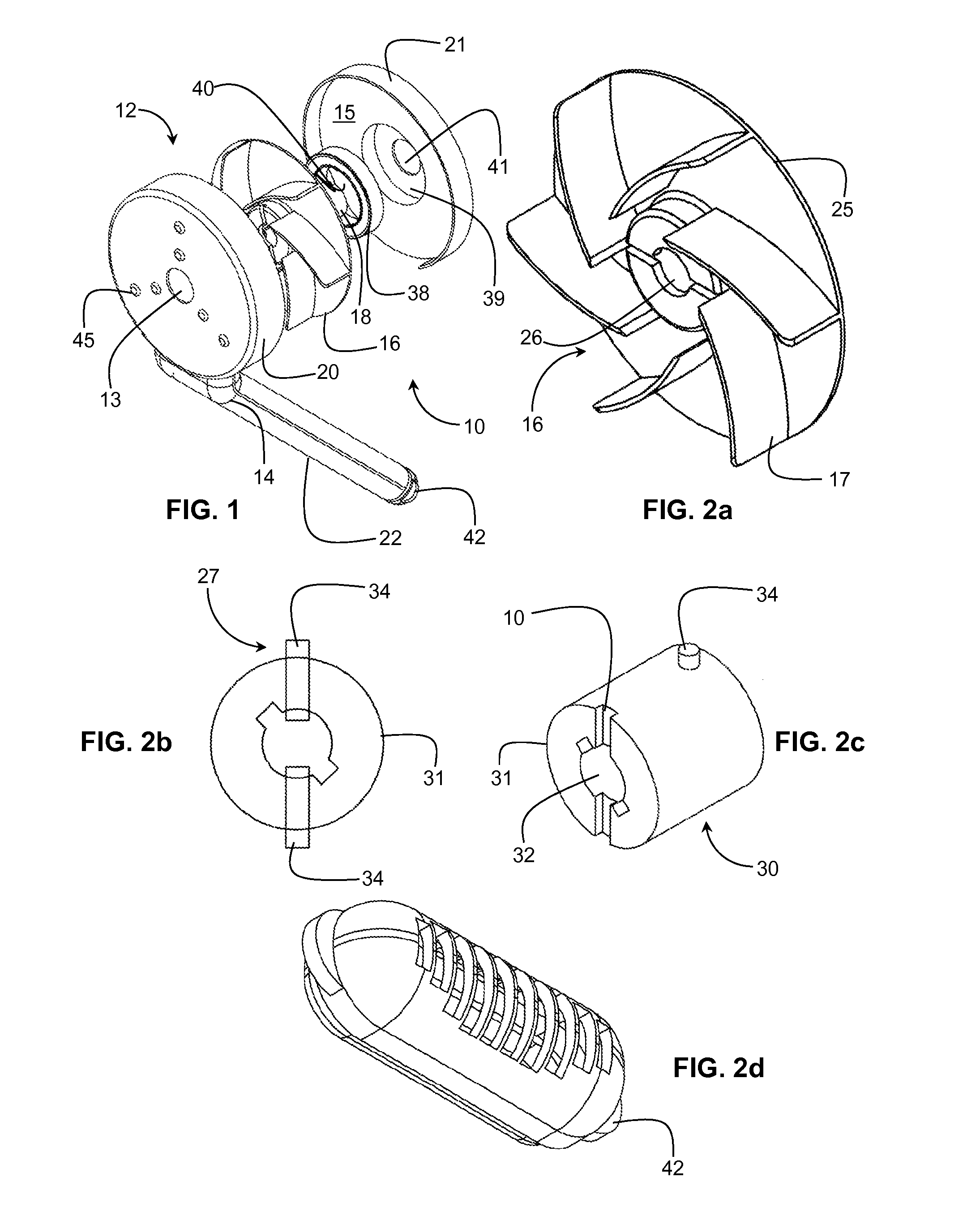
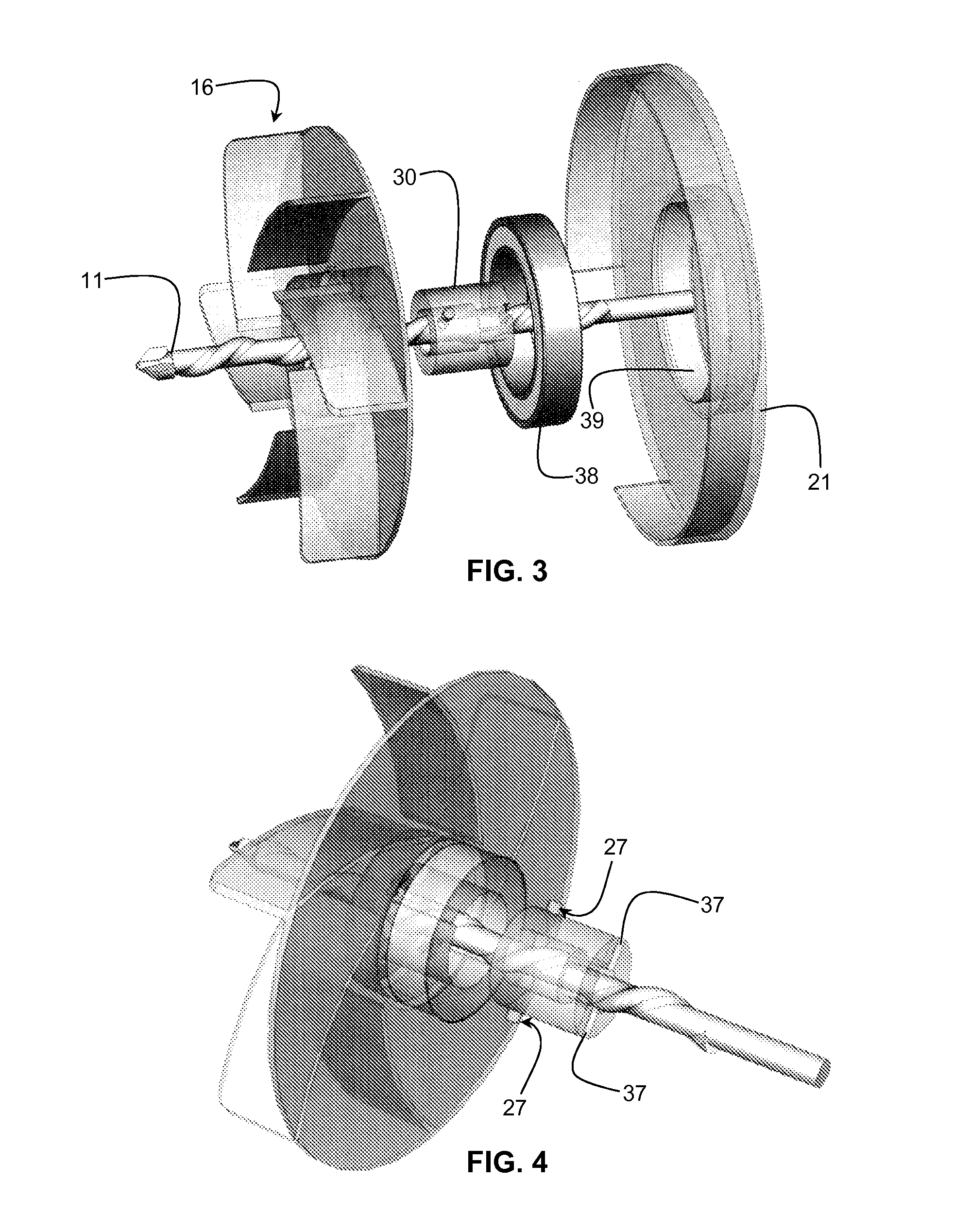
[0034]With reference to the figures, there is shown a dust extraction device 10 for fitting directly on to an elongate drill bit 11 of a rotary power tool (not shown). The dust extraction device 10 comprises a casing 12 having an inlet 13 and an outlet 14 and defining an interior cavity 15, said inlet 13 and outlet 14 communicating with the interior cavity 15 for permitting air flow into the interior space from the inlet to the outlet. A fan element 16 has a plurality of impellers 17 radially attached to a central hub 18 that is adapted for rotation within and independent of the casing for inducing air flow within the casing from the inlet to the outlet when the fan element rotates. The hub 18 is adapted for engaging the drill bit 11 in a manner that permits rotation of the hub as well a...


PUM

PropertyMeasurementUnit
rotationaaaaaaaaaa
diameteraaaaaaaaaa
internal diameteraaaaaaaaaa

Abstract

A dust extraction device (10) for a rotary power tool having an elongate rotating drill bit (1) for operating on a work surface includes a casing (12) having an inlet (13) and an outlet (14) and defining an interior cavity (15). A fan element (16) having a plurality of impellers (17) and a central hub (18) is adapted for rotation within and independent of the casing for inducing air flow within the casing from the inlet to the outlet when the fan element rotates, the hub being adapted for engaging the drill bit (11) in a manner that permits rotation of the hub as well as axial movement of the drill bit relative to the hub during rotation of the drill bit. Rotation of the drill bit results in air flow to remove debris from the work surface to the outlet without rotating the casing.

Description

FIELD OF THE INVENTION[0001]The present invention relates to a dust extraction device for a rotating drill cutting tool.BACKGROUND OF THE INVENTION[0002]A drilling procedure is usually accompanied by small-sized particle residues extracted from the drilled material e.g. dust, sawdust, metal particles, etc. The vibrations associated with the operation of a power drill and the rotation of the cutting tool tend to vigorously disperse these residues all around the working environment, forcing the user to clean and remove the scattered dust and residues.[0003]It is therefore known to provide either a dust collector, which is inherently of a passive type, or a dust extractor, which is inherently of an active type. Representative patents relating to dust collectors include U.S. Pat. Nos. 6,102,631; 4,251,171; 5,061,123 and 5,653,561. The devices described in these patents typically include a receptacle mounted on the drill bit having an open end that is held flush with a work surface being...

Claims


Application Information

Patent Timeline
Patent Type & Authority Patents(United States)
IPC IPC(8): B23Q11/00B23B45/00
CPCB23Q11/0046B23B45/003B23B2270/30B23B2270/62B23Q11/0042Y02P70/171Y10T408/44Y10T408/50Y02P70/10
Inventor MAGEN, EREZHARONYAN, OREN
Owner HAVIV LIOR
Why Eureka
Try Eureka