
Method and apparatus for an isolating structure

Active Publication Date: 2016-08-09
HANKING ELECTRONICS LTD
View PDF10 Cites 7 Cited by
  • Summary
  • Abstract
  • Description
  • Claims
  • Application Information

AI Technical Summary

Benefits of technology

This patent describes a way to make a mechanical filter to reduce shock from impact during a packaging process. The filter is made by etching a copper frame or using a molded and routed device that creates a spring apparatus. This helps to protect the sensitive components of the device from damage during shipment or impact.

Problems solved by technology

MEMS sensing products can fail as a result of stresses and external mechanical shock such as rock impingement.
For critical applications this can have catastrophic consequences.
The location of the gyroscope device makes it particularly prone to impact by debris from the road.
Even within the housing a rock, pebble or other road debris can impact the housing of the gyroscopic device and impair its operation.
This impact will then cause the drive mass to touch the substrate resulting in a loss of lock on the drive signal.
This impact causes a brief failure of the gyroscope device.
However, that brief failure can occur at a critical time and by the time the gyroscope device has recovered the vehicle could have already rolled over.
Unfortunately, the functioning of the gyroscope device is even more critical on road surfaces with a lot of debris, for example a dirt road or a road covered in pebbles.
On those types of surfaces there are more likely to be stability control or roll-over issues.
Also, those surfaces are more prone to impact and thus failure of the gyroscopic device.

Method used


Image

  • Method and apparatus for an isolating structure
  • Method and apparatus for an isolating structure
  • Method and apparatus for an isolating structure

Examples


Embodiment Construction

[0027]The following description is set forth for purpose of explanation in order to provide an understanding of the invention. However, it is apparent that one skilled in the art will recognize that embodiments of the present invention, some of which are described below, may be incorporated into a number of different systems and devices. The embodiments of the present invention may be present in hardware, software or firmware. Structures shown below in the diagram are illustrative of exemplary embodiments of the invention and are meant to avoid obscuring the invention. Furthermore, connections between components within the figures are not intended to be limited to direct connections. Rather, data between these components may be modified, re-formatted or otherwise changed by intermediary components.

[0028]Reference in the specification to “one embodiment”, “in one embodiment” or “an embodiment” etc. means that a particular feature, structure, characteristic, or function described in c...


PUM


Abstract

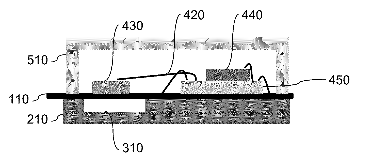
The present invention relates to a method and apparatus for an isolating structure. Embodiments of the present invention provide a robust packaging process and a mechanical filter to reduce the mechanical shock from impact. The mechanical filter can be integrated within the package substrate as part of the packaging process, reducing the assembly complexity.

Description

BACKGROUND[0001]A. Technical Field[0002]This invention relates generally to semiconductor manufacturing and packaging and more specifically to semiconductor manufacturing in MEMS (Microelectromechanical systems) sensing products.[0003]B. Background of the Invention[0004]MEMS sensing products can fail as a result of stresses and external mechanical shock such as rock impingement. For critical applications this can have catastrophic consequences. One field for which the consequences are catastrophic is in the field of automotive stability control, automotive air bag systems is another field and engine pressure management is yet another field for which consequences are catastrophic.[0005]Automobiles use an inertial sensing device or a gyroscope device to assist in stability control and roll-over detection. The proper operation of the gyroscopic device is critical to the safety of the passengers of the automobile in order to detect a potentially dangerous condition, such as loss of cont...

Claims


Application Information

Patent Timeline
IPC IPC(8): H01L29/84B81B7/00H01L21/52
CPCB81B7/0058B81B7/0048B81B2207/07H01L2224/48137
Inventor DESAI, HEMANTPATEL, VIRESH P.
Owner HANKING ELECTRONICS LTD
Learn More