Optical sensing system for determining the position and/or shape of an associated object

a position and/or object technology, applied in the field of minimally invasive healthcare procedures, can solve the problems of poor spatial resolution, low signal strength, easy breakage, etc., and achieve the effects of improving the shape and/or position sensing system, and reducing the risk of injury

Active Publication Date: 2016-08-16
KONINK PHILIPS ELECTRONICS NV
View PDF9 Cites 39 Cited by
  • Summary
  • Abstract
  • Description
  • Claims
  • Application Information

AI Technical Summary

Benefits of technology

[0022]The invention is particularly, but not exclusively, advantageous for obtaining an optical system where the Fiber Bragg grating(s) may be effectively continuous along the optical fiber leaving no gaps so that every position gives rise to a detectable reflection, and achieving that the reflection spectrum may encompass a wavelength span equaling the wavelength scan, or ‘sweep’, of an optical source in the reflectometer.
[0028]In one embodiment, the at least one optical fiber core (10) may have a single fiber Bragg grating (FBG, 8) extending along the said full length where the position and / or shape is be to determined of said object, possibly more than one optical fiber core may have a FBG extending along the length. This is a so-called in-homogeneous solution within the context of the present application, and is a particular advantageous solution amongst other things due to relative ease of manufacturing. In a further embodiment, the single fiber Bragg grating may be chirped in a plurality of regions along the said full length so that every sampling point in the optical core has an effective, separate resonance wavelength, each sampling point being detectable in said wavelength scan. Notice that the chirping, i.e. change in periodicity of the grating, may be linear or non-linearly. In one embodiment, the said plurality of regions may be partly overlapping each other, the overlap region may be approximately the same size or it may vary from one overlapping region to the next region. The overlap may advantageously increase stability of the strain measurements because possible gaps between the gratings are avoided or minimized.
[0030]Preferably, the chirping length within the said regions is chosen so that the corresponding coherence length of the phase is longer than the step length (Δz) between consecutive sampling points because this will significantly reduce sensitivity to vibrations and / or temperature fluctuations, e.g. more than one order of magnitude as explained in more detail below.

Problems solved by technology

Brillouin scattering cannot be employed in an interferometric measurement technique and leads to a poor spatial resolution.
For shape sensing this has the disadvantage that the signal strength is rather low.
This termination, however, is fragile and breaks of easily, so that integration of the fiber in medical devices has a low yield.
Moreover, this kind of termination has the side effect that the last 5-10 mm of the fiber cannot be shape tracked.
The rejection ratio of most circulators is too low for sensing using Rayleigh scattering.
Reflections at these connectors deteriorate the Rayleigh signals and are prone to give rise to cross talk effects.
Current systems (e.g. Luna 3-rd generation) will not be able to function properly with more than one multi-core connector.
Luckily, it reproduces so that phase tracking with respect to a reference signal is possible. FIG. 1 does, however, reveal that minute shifts in length will completely destroy the coherence of the phase difference between shape measurement and reference.
An inherent disadvantage is that for typical FBG configurations, the detector of the reflectometer must have a relatively large dynamic range to encompass the information in the ‘wings’ of the spectral band.

Method used


Image

  • Optical sensing system for determining the position and/or shape of an associated object
  • Optical sensing system for determining the position and/or shape of an associated object
  • Optical sensing system for determining the position and/or shape of an associated object

Examples


Embodiment Construction

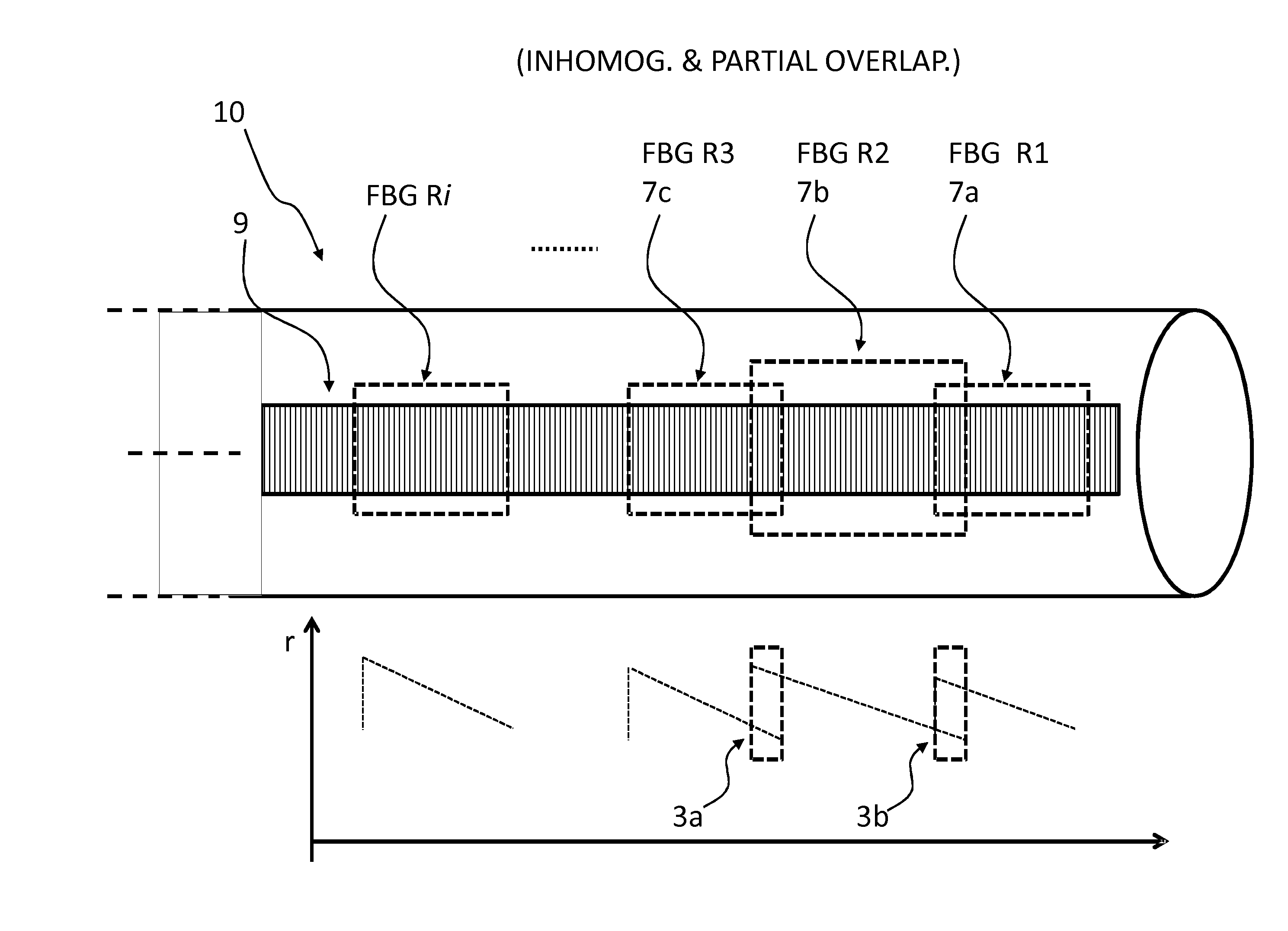
[0063]FIG. 10 shows a schematic illustration of an optical position and / or shape sensing system 1 according to the present invention. The optical sensing system 1 is adapted for determining the position and / or shape of an associated object O. The system comprises one or more optical fibers 10 for spatial fixation on, in, or to said associated object O, each optical fiber having one or more optical fiber cores, cf. FIG. 11 and forwards.

[0064]Furthermore, a plurality of optical fiber cores, not shown here, have one or more fiber Bragg gratings (FBG) extending along the full length of said optical fiber cores where the position and / or shape is be to determined of said object O.

[0065]A reflectometer REFL 12 is optically connected, e.g. via auxiliary optical fiber 11 adapted for that purpose, to said one or more optical fibers 10, the reflectometer 12 being optical arranged for measuring the strain at a number of sampling points along the plurality of optical fiber cores. Possibly, more ...


PUM

PropertyMeasurementUnit
coherence lengthaaaaaaaaaa
Riaaaaaaaaaa
lengthaaaaaaaaaa

Abstract

The present invention relates to an optical sensing system (1) for determining the position and / or shape of an associated object (O), the system comprises an optical fibers (10) having one or more optical fiber cores (9) with one or more fiber Bragg gratings (FBG, 8) extending along the full length where the position and / or shape is be to determined of said object (O). A reflectometer (REFL, 12) measures strain at a number of sampling points along the optical fiber cores, and a processor (PROC, 14) determines the position and / or shape based on said measured strains from the plurality of optical fiber cores. The fiber Bragg grating(s) (FBG, 8) extends along the full length of said optical fiber cores (9), the fiber core having a spatially modulated reflection (r) along the said full length of the optical fiber core so that the corresponding reflection spectrum is detectable in said wavelength scan. Thus, the fiber Bragg grating(s) may be effectively continuous along the optical fiber leaving no gaps so that every position gives rise to a detectable reflection, and achieving that the reflection spectrum may encompass a wavelength span equaling the wavelength scan, or ‘sweep’, of an optical source in the reflectometer.

Description

CROSS-REFERENCE TO PRIOR APPLICATIONS[0001]This application is the U.S. National Phase application under 35 U.S.C. §371 of International Application Serial No. PCT / IB2013 / 051905, filed on Mar. 11, 2013, which claims the benefit of U.S. Application Ser. No. 61 / 611,646, filed on Mar. 16, 2012, and U.S. Application Ser. No. 61 / 657,176, filed on Jun. 8, 2012. These applications are hereby incorporated by reference herein.BACKGROUND OF THE INVENTION[0002]In many minimally invasive healthcare procedures, it is advantageous to track the medical devices such as guide wires and catheters. Optical shape sensing enables this by measuring and analyzing the light reflected from all positions of a multi core optical fiber built into the elongated medical device. When interferometer is used a full distribution of strain along the fiber is obtained, which can be converted into shape. A description of the method can be found in patent application US 2011 / 0109898 entitled “Optical position and / or sha...

Claims


Application Information

Patent Timeline
Patent Type & Authority Patents(United States)
IPC IPC(8): G01B11/14G01L1/24G01B11/24G01B11/16G01B9/02
CPCG01B11/16G01B9/02049G01B11/14G01B11/24G01L1/246G01B9/02004G01B11/18G01M11/025G01M11/3136
Inventor 'T HOOFT, GERT WIMLEISTIKOW, MEREL DANIELLEHORIKX, JEROEN JAN LAMBERTUSMARELL, MILAN JAN HENRI
Owner KONINK PHILIPS ELECTRONICS NV
Why Eureka
Try Eureka