Multi-sensor control circuit and method for using the same

a multi-sensor control and control circuit technology, applied in the direction of liquid/fluent solid measurement, instruments, tobacco, etc., can solve the problems of electronic cigarettes not working, sensors malfunctioning, hardware cost increase, etc., and achieve the effect of reducing the failure rate of electronic cigarettes

Inactive Publication Date: 2016-08-16
HUIZHOU KIMREE TECH
View PDF6 Cites 36 Cited by
  • Summary
  • Abstract
  • Description
  • Claims
  • Application Information

AI Technical Summary

Benefits of technology

[0026]By implementing the multi-sensor control circuit of the present application, the following advantages can be achieved: the multi-sensor control circuit of the present application is used in an electronic cigarette and includes a control module, at least two inhalation sensors, and at least two unidirectional circuits corresponding to the inhalation sensors. A sensing voltage signal outputted from each inhalation sensor is filtered by a corresponding unidirectional circuit and thereby becomes a unidirectional voltage signal. Output terminals of the unidirectional circuits are all connected to a same input pin of the control module. Upon receiving a unidirectional voltage signal outputted from any one of the unidirectional circuits, the control module controls the electronic cigarette to work. In this way, the failure rate of the electronic cigarette can be decreased. Furthermore, the multi-sensor control circuit of the present application neither requires too complicated hardware nor occupies too much software resource.

Problems solved by technology

The tobacco tar may cause the sensors to malfunction, and the electronic cigarettes may be unable to work due to the malfunctions of the sensors.
However, the connection method of the multi-sensor control circuit requires occupying more I / O interfaces or pins of the microcontroller, and therefore the hardware cost may increase.
Furthermore, controlling the smoking sensors occupies much software resource of the microcontroller.
Therefore, the prior art has drawbacks and needs to be improved.

Method used


Image

  • Multi-sensor control circuit and method for using the same
  • Multi-sensor control circuit and method for using the same
  • Multi-sensor control circuit and method for using the same

Examples


first embodiment

[0044]Referring to FIG. 3, a circuit diagram of a multi-sensor control circuit of the present application is shown.

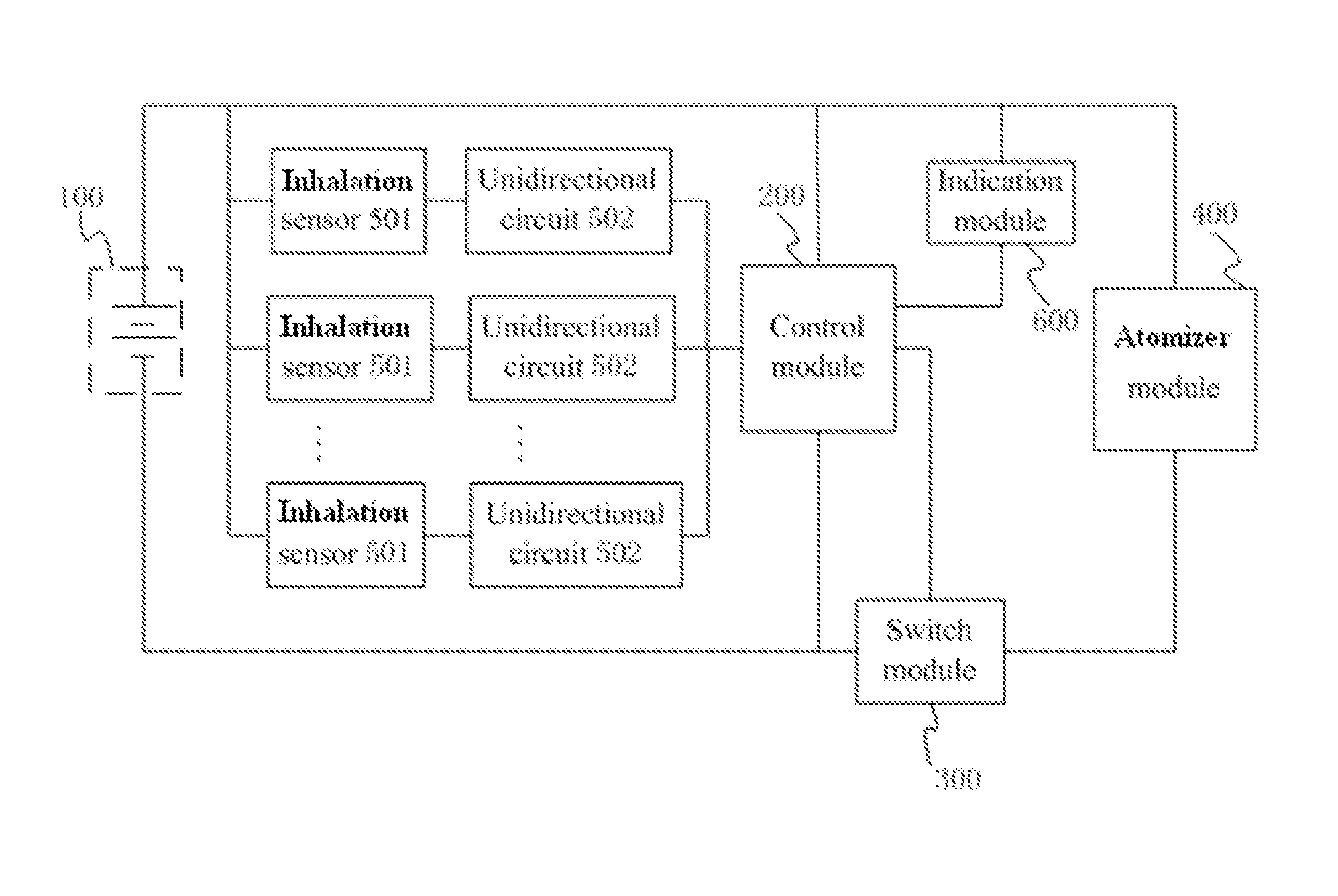
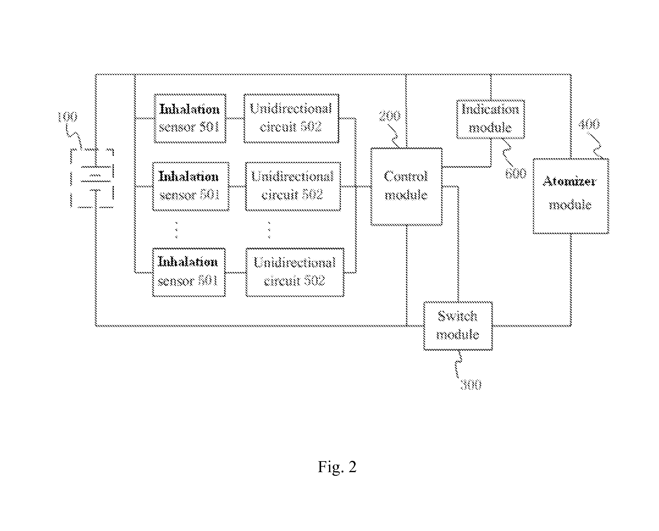
[0045]According to FIG. 2 and FIG. 3, in the multi-sensor control circuit of the first embodiment of the present application, the control module 200 includes a microprocessor U1, and the type of the microprocessor U1 is SN8P2711B. A second pin of the microprocessor U1 acts as the input pin of the control module 200 that is configured to connect to all of the unidirectional circuits 502.

[0046]The type of all of the inhalation sensors 501 is S087. Accordingly, each of the inhalation sensors 501 includes a first sensor pin, a second sensor pin, and a third sensor pin. Each of the unidirectional circuits 502 includes a diode D1, and the diode D1 is advantageously a Schottky diode. In this embodiment, the number of the inhalation sensors 501 is two, and the number of the diodes D1 is also two. The multi-sensor control circuit further includes a pull-down resistor R4.

[0047]In...

second embodiment

[0053]Referring to FIG. 4, a circuit diagram of a multi-sensor control circuit of the present application is shown.

[0054]The second embodiment differs from the first embodiment in that: in the second embodiment, negative voltage signals outputted by the inhalation sensors 501 are considered as effective sensing voltage signals. Therefore, in the second embodiment, reverse diodes D3 replace the diodes D1 of the unidirectional circuits 502, and a pull-up resistor R6 replaces the pull-down resistor R4.

[0055]In particular, the first sensor pin of each of the inhalation sensors 501 is connected to a positive pole of the battery 100, the second sensor pin of each of the inhalation sensors 501 is connected to a cathode of the diode D3 of the unidirectional circuit 502 corresponding to the inhalation sensor 501 and acts as an output terminal of the inhalation sensor 501, and the third sensor pin of each of the inhalation sensors 501 is grounded. An anode of the diode D3 of each of the unidi...


PUM


Abstract

A multi-sensor control circuit used in an electronic cigarette comprises a control module, at least two inhalation sensors, and at least two unidirectional circuits corresponding to the inhalation sensors. An output terminal of each inhalation sensor is connected to an input terminal of a corresponding unidirectional circuit, and output terminals of the unidirectional circuits are all connected to a same input pin of the control module. Each inhalation sensor outputs a sensing voltage signal to the corresponding one of the unidirectional circuits upon sensing airflow. Each unidirectional circuit filters the sensing voltage signal received from a corresponding inhalation sensor to generate a unidirectional voltage signal, and outputs the unidirectional voltage signal to the input pin of the control module. The control module controls the electronic cigarette to work upon receiving the unidirectional voltage signal outputted from any unidirectional circuit.

Description

CROSS-REFERENCE TO RELATED APPLICATIONS[0001]This non-provisional application claims priority under 35 U.S.C. §119(a) on Patent Application No. 201320595571.5, filed in P.R. China on Sep. 25, 2013, the entire contents of which are hereby incorporated by reference.FIELD OF THE INVENTION[0002]The present application relates to the field of daily electronic products, and more particularly, relates to a multi-sensor control circuit and a method for using the same.BACKGROUND OF THE INVENTION[0003]Sensors of electronic cigarettes may be often soaked by tobacco tar. The tobacco tar may cause the sensors to malfunction, and the electronic cigarettes may be unable to work due to the malfunctions of the sensors.[0004]Aiming at the aforementioned problem, a method for using a plurality of smoking sensors in one electronic cigarette has been provided. Referring to FIG. 1, a structural schematic view of a multi-sensor control circuit in the prior art is shown. The multi-sensor control circuit is...

Claims


Application Information

Patent Timeline
Patent Type & Authority Patents(United States)
IPC IPC(8): A24F47/00G01F25/00G01F1/00A24F40/40A24F40/51A24F40/60
CPCG01F25/0007G01F1/00A24F47/008A24F40/51A24F40/60A24F40/40G01F25/10
Inventor XIANG, ZHIYONG
Owner HUIZHOU KIMREE TECH
Why Eureka
Try Eureka