Lighting device, projector including the same, and lighting method
a technology of lighting device and projector, which is applied in the direction of picture reproducers, picture reproducers using projection devices, instruments, etc., can solve the problems of inability to achieve blue light of a desired tone and color purity, inability to improve the color purity of blue light, and inability to reproduce an accurate color image. achieve the effect of high color purity
- Summary
- Abstract
- Description
- Claims
- Application Information
AI Technical Summary
Benefits of technology
Problems solved by technology
Method used
Image

Examples
embodiment 1
(Embodiment 1)
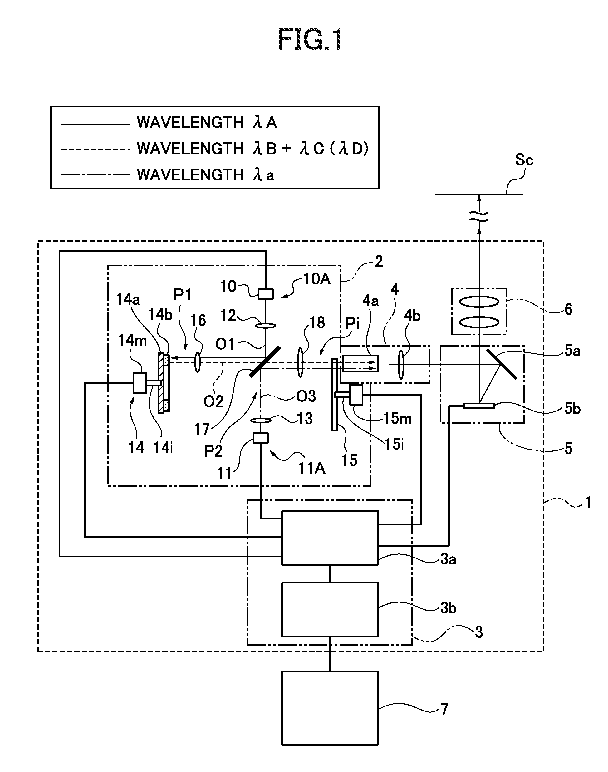
[0027]FIG. 1 is an optical view illustrating a lighting device and a projector including the light device according to Embodiment 1 of the present invention. As illustrated in FIG. 1, a projector 1 according to Embodiment 1 includes a lighting device 2, a controller 3, a light-guiding optical system 4, an image generator 5, and a projection optical system 6. The projector 1 is configured to project an image on a screen Sc such as a projection surface, so as to display an enlarged image.
[Lighting Device 2]
[0028]The lighting device 2 sequentially emits red light, green light, and blue light on a time-division base, or combines (mix) these so as to emit the combined light. The lighting device 2 emits light (light flux) of each color toward the after-described light tunnel 4a of the light-guiding optical system 4. The details of the configuration of the lighting device 2 will be described later.
[Light-Guiding Optical System 4]
[0029]The light-guiding optical system 4 guides...
embodiment 2
(Embodiment 2)
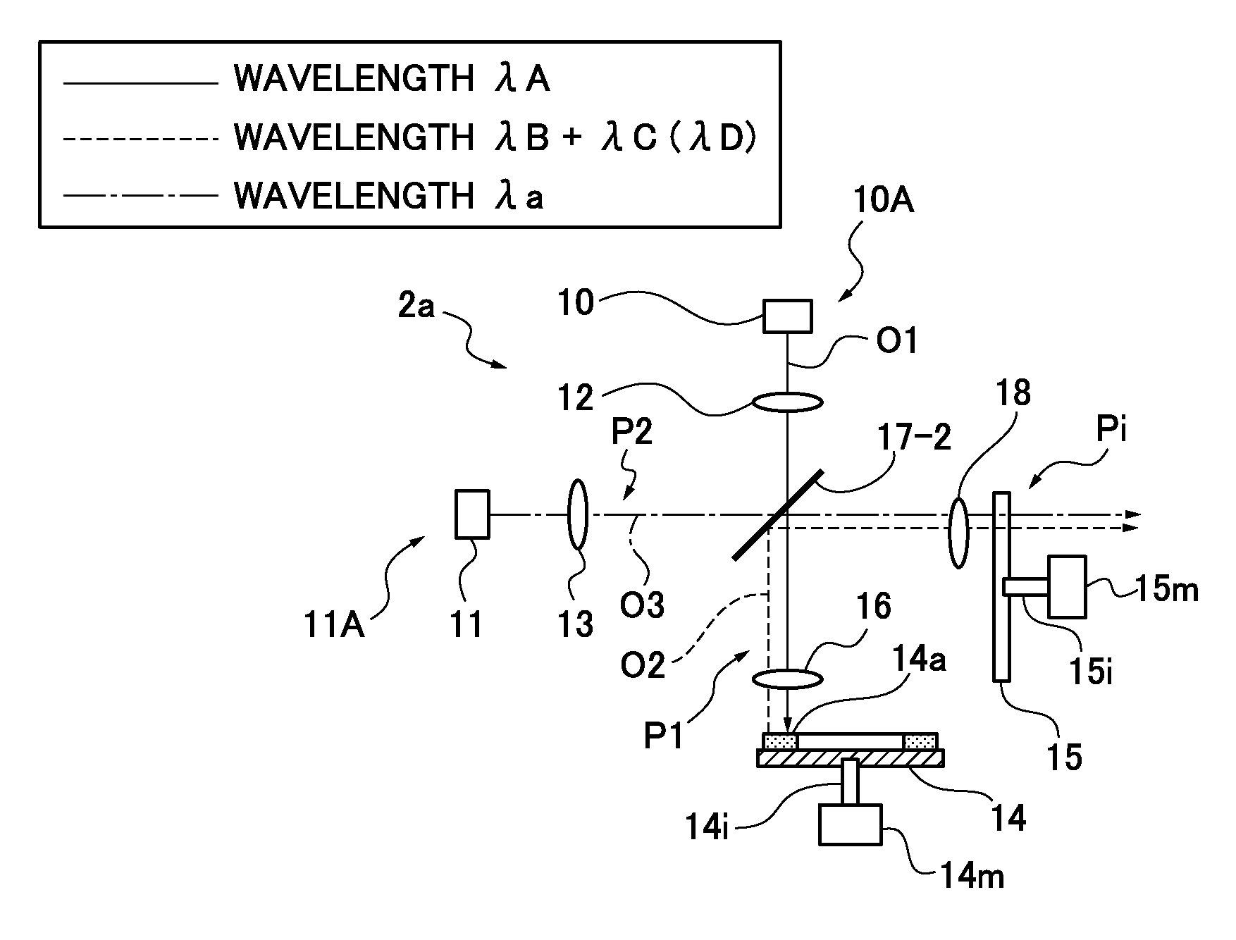
[0082]Next, a lighting device of Embodiment 2 will be described with reference to FIG. 5. FIG. 5 provides an optical view of a lighting device 2a according to Embodiment 2. The lighting device 2a of Embodiment 2 includes a basic configuration similar to that of the lighting device 2 of Embodiment 1 illustrated in FIG. 1 except that a dichroic mirror 17-2 which transmits the blue light (excitation light) of λA and the blue light of λa, and reflects the yellow fluorescence of λD is used instead of the dichroic mirror 17 in Embodiment 1 which reflects the blue light (excitation light) of λA and the blue light of λa, and transmits the yellow fluorescence of λD. Thus, the detailed description of the configurations similar to those in Embodiment 1 will be omitted. This is the same as in the following embodiments.
[0083]The lighting device 2a according to Embodiment 2 includes a first lighting optical system 10A using a first light source 10 and a second lighting optical syste...
embodiment 3
(Embodiment 3)
[0096]Next, a projector including a lighting device according to Embodiment 3 will be described with reference to FIGS. 6, 7. FIG. 6 provides an enlarged plan view of a light transmission control wheel 15-2 for use in the lighting device according to Embodiment 3, and a view as seen from the light-incident side. FIG. 7 provides a view illustrating a relationship between the control, which emits red (R), green (G), blue (B), and yellow (Y) light from the lighting device in Embodiment 3, and an image frame. The projector including the lighting device of Embodiment 3 includes a basic configuration similar to that of the projector 1 including the lighting device 2 in Embodiment 1 illustrated in FIG. 1 except that the light transmission control wheel 15-2 illustrated in FIG. 6 is used instated of the light transmission control wheel 15. Thus, the description of the configurations similar to those in Embodiment 1 will be omitted.
[0097]The light transmission control wheel 15-...
PUM
 Abstract
Description
Claims
Application Information
 - R&D
- Intellectual Property
- Life Sciences
- Materials
- Tech Scout
- Unparalleled Data Quality
- Higher Quality Content
- 60% Fewer Hallucinations
Browse by: Latest US Patents, China's latest patents, Technical Efficacy Thesaurus, Application Domain, Technology Topic, Popular Technical Reports.
© 2025 PatSnap. All rights reserved.Legal|Privacy policy|Modern Slavery Act Transparency Statement|Sitemap|About US| Contact US: help@patsnap.com