Electromagnetic wave propagation disruption device and method for producing same

a technology of electromagnetic wave propagation and device, which is applied in the direction of antenna details, antenna couplings, electrical equipment, etc., can solve the problems of not being able to achieve optimal 3d metamaterial structure size and difficult to envisage the modification of this type of behavior, and achieve the effect of increasing the capacitive effect of the cell

Active Publication Date: 2016-08-16
COMMISSARIAT A LENERGIE ATOMIQUE ET AUX ENERGIES ALTERNATIVES
View PDF14 Cites 79 Cited by
  • Summary
  • Abstract
  • Description
  • Claims
  • Application Information

AI Technical Summary

Benefits of technology

[0024]By means of the invention, a novel way to modify the behavior of a metamaterial is proposed. More specifically, an additional setting is proposed, this setting being extrinsic to the metamaterial structure. Indeed, by interconnecting the conductive elements of the metamaterial to each other using a plurality of electrically insulated networks, phase shifts are created between the electrically connected conductive elements and it was surprisingly observed that an optimal combination of at least two different phase shifts between elements from one network to another makes it possible to reduce coupling between planar antennas positioned around a metamaterial of this type further. This results in superior efficiency of these metamaterials, particularly but not merely when they are used as an EBG structure.
[0028]In this way, with the use of active elements such as adjustable phase shift devices, for example diodes, during the interconnection of the conductive elements to each other, it becomes possible to adjust the phase shifts according to the application to be optimized merely by setting these active elements while retaining the structure of the metamaterial and without affecting the established dimensioning of the interconnection networks.
[0036]Also optionally, the metamaterial structure comprises two overlaid layers of conductive elements arranged on a top face of the substrate, each of these layers comprising a plurality of conductive elements separated from each other and distributed in an array along m rows and n columns, these two layers being separated from each other along a perpendicular direction to the top face of the substrate by a predetermined distance, the conductive elements of the first layer being arranged in a staggered fashion relative to the conductive elements of the second layer so as to increase the capacitive effect of the cell.

Problems solved by technology

These parameters being defined during the design of the EBG structure, it is not easy to envisage the modification of the behavior of this type of structure after the production thereof.
Furthermore, this type of 3D metamaterial structure is not optimal in respect of size when used in a planar antenna array or in any system wherein a compact size of the devices is sought.

Method used


Image

  • Electromagnetic wave propagation disruption device and method for producing same
  • Electromagnetic wave propagation disruption device and method for producing same
  • Electromagnetic wave propagation disruption device and method for producing same

Examples


Embodiment Construction

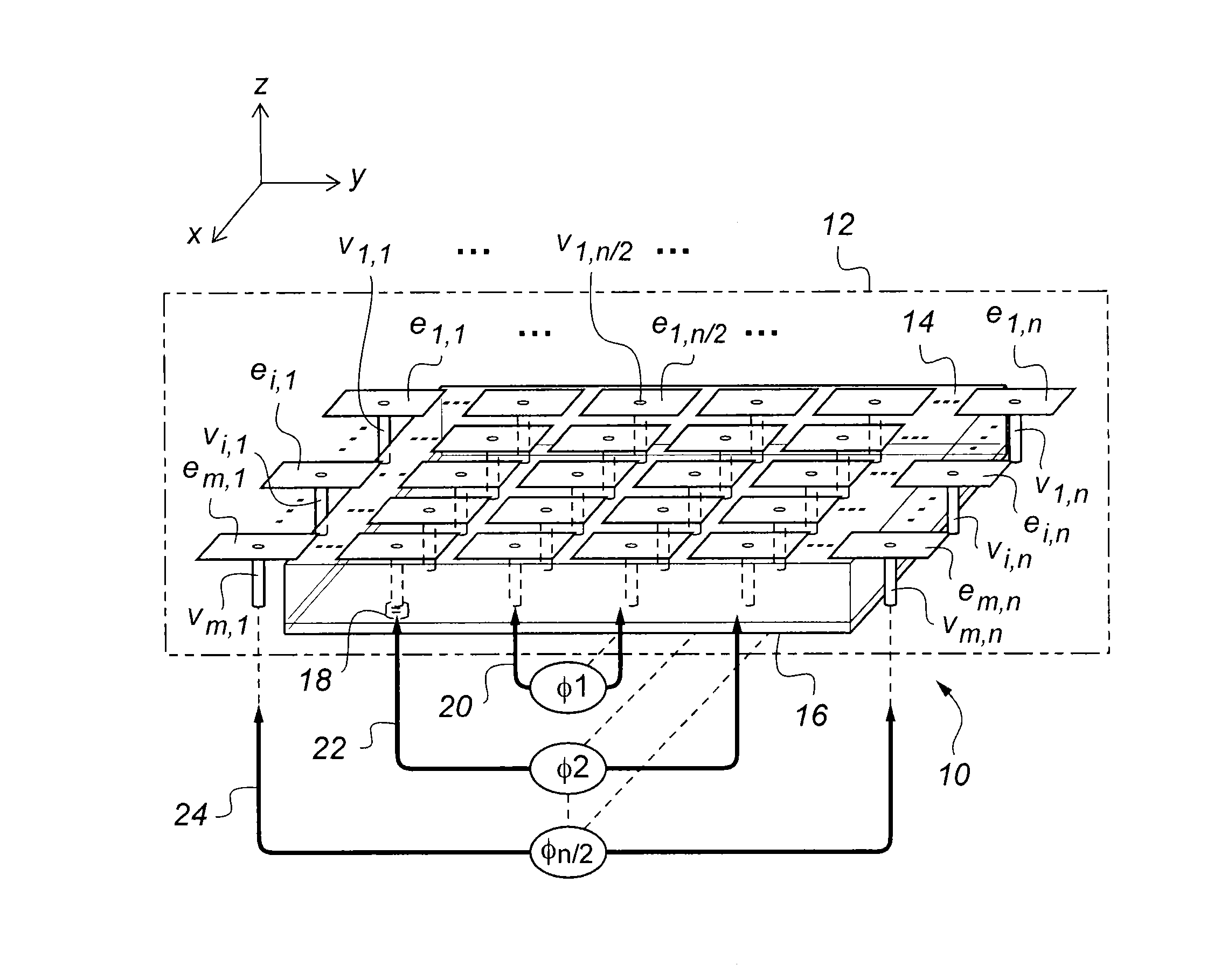
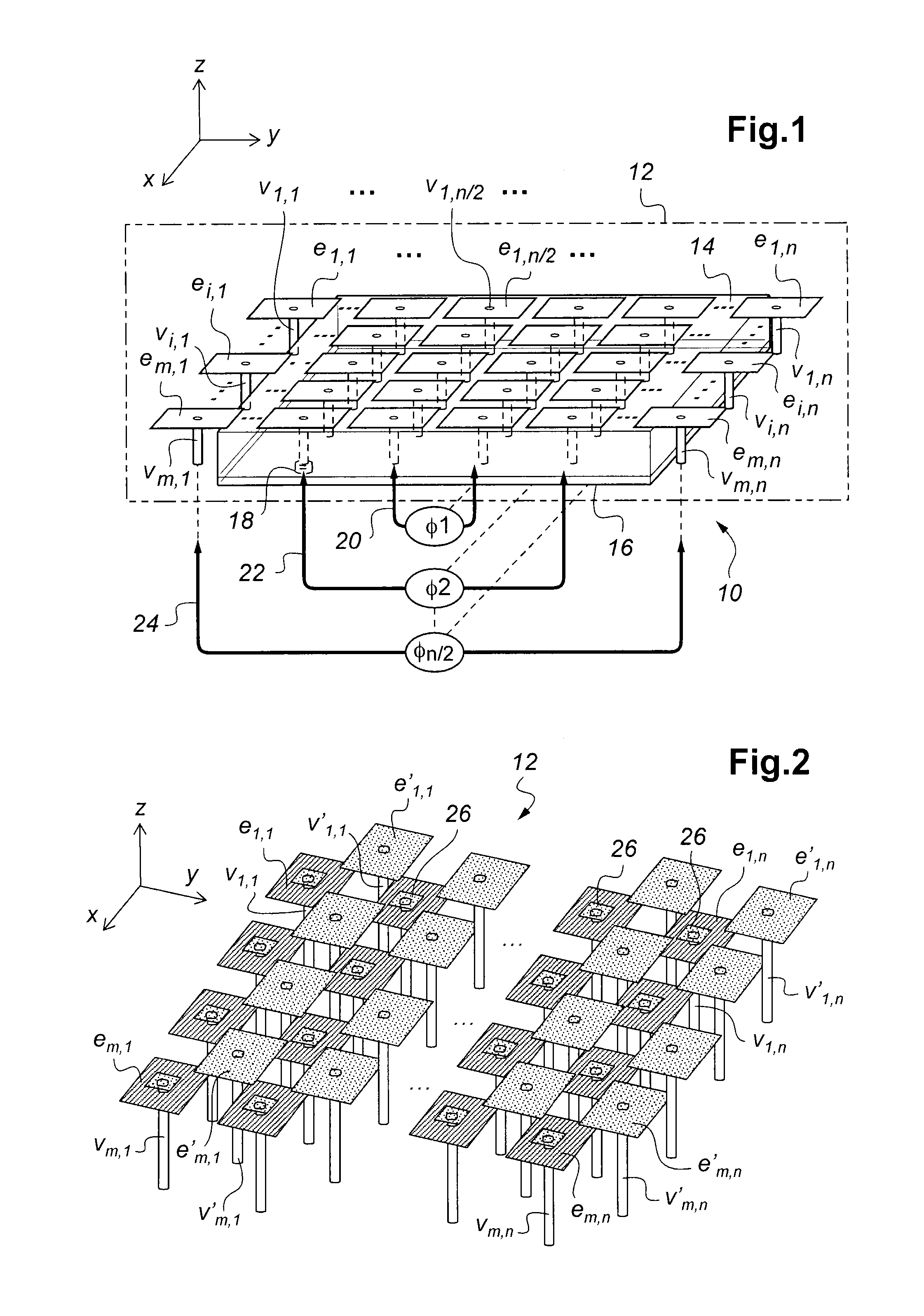
[0054]FIG. 1 represents a sectional perspective view of the overall structure of an electromagnetic wave propagation disruption device 10 with a metamaterial structure 12, according to one possible embodiment of the invention. This device may for example be positioned between two elements of a planar antenna defined on the same substrate to limit the surface waves between these two elements.

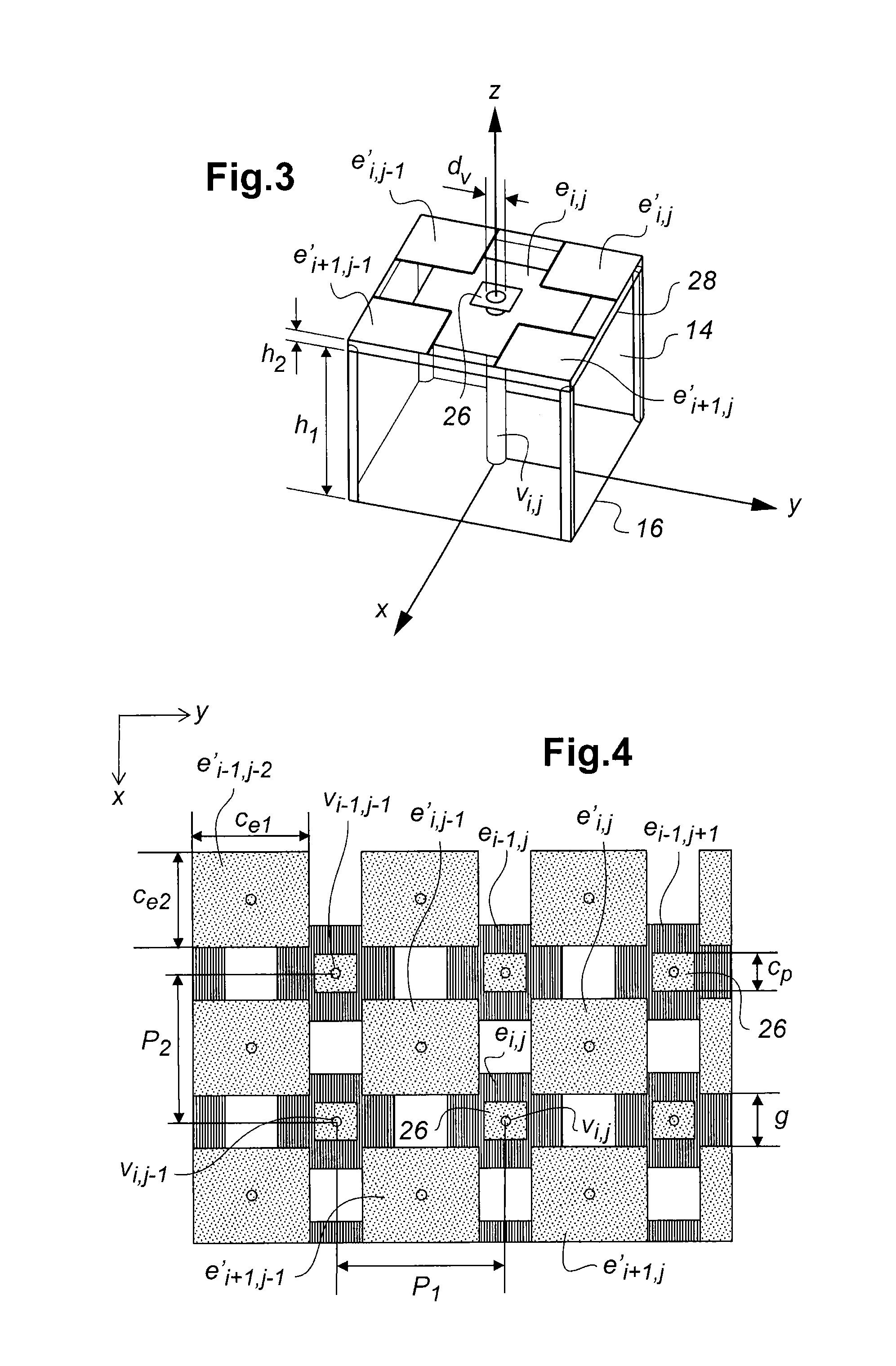
[0055]In this embodiment, the metamaterial structure 12 is of the mushroom type and comprises a plurality of conductive elements e1,1, . . . , ei,j, . . . , em,n in a rectangular shape, separated from each other and arranged on a top face of a substrate 14 made, for example, of dielectric material. This substrate may be an epoxy-based insulating material, an insulating material well known to those skilled in the art, for example FR4 type with a relative permittivity value εR of approximately 4.4. The conductive elements e1,1, . . . , ei,j, . . . , em,n are distributed on the substrate 14 in an ar...


PUM

PropertyMeasurementUnit
relative permittivityaaaaaaaaaa
heightaaaaaaaaaa
distanceaaaaaaaaaa

Abstract

An electromagnetic wave propagation disruption device with a metamaterial structure including: a plurality of conductive elements arranged on a top face of a substrate; a plurality of interconnection networks electrically interconnecting at least some of these conductive elements, wherein these networks are not electrically connected to each other. At least two of these networks are dimensioned differently to each other, thus involving that distances between interconnected conductive elements are different from one network to another, to generate phase shifts, between the conductive elements interconnected thereby, different from one network to the other. A ground plane with holes is arranged on a bottom face of the substrate and metallic vias are formed in the substrate, each of them including an upper end in contact with a conductive elements and a lower end arranged facing one of the holes of the ground plane, with no electrical contact with the ground plane.

Description

[0001]The present invention relates to an electromagnetic wave propagation disruption device. It also relates to a method for producing this device.BACKGROUND OF THE INVENTION[0002]The invention applies more particularly to an electromagnetic wave propagation disruption device with a metamaterial structure comprising:[0003]a plurality of conductive elements separated from each other and arranged on a substrate,[0004]a plurality of interconnection networks electrically interconnecting at least some of these conductive elements, these interconnection networks not necessarily being electrically connected to each other.[0005]The use of antennas in communication, monitoring or satellite navigation systems is inescapable. However, in this type of system, the space available for these devices is reduced and involves a need for antenna miniaturization.[0006]Due to the reduced size thereof, planar antennas are good candidates for this type of system. As a general rule, a planar antenna compr...

Claims


Application Information

Patent Timeline
Patent Type & Authority Patents(United States)
IPC IPC(8): H01Q1/52H01Q15/00
CPCH01Q1/525H01Q1/526H01Q15/0066H01Q1/523H01Q15/008Y10T29/4902
Inventor PINTOS, JEAN-FRANCOISEL BOUAYADI, OSSAMA
Owner COMMISSARIAT A LENERGIE ATOMIQUE ET AUX ENERGIES ALTERNATIVES
Why Eureka
Try Eureka