Negative pressure wound closure device

a wound closure and negative pressure technology, applied in the field of negative pressure wound closure devices, can solve the problems that prior negative pressure devices did not assist in wound closure, and achieve the effects of reducing the need for repetitive replacement, facilitating wound closure, and improving healing ra

Active Publication Date: 2016-08-23
UNIV OF MASSACHUSETTS
View PDF366 Cites 45 Cited by
  • Summary
  • Abstract
  • Description
  • Claims
  • Application Information

AI Technical Summary

Benefits of technology

[0004]The present invention relates to a negative pressure wound closure device that specifically exerts force at the edges of the wound to facilitate closure of the wound. The device operates to reduce the need for repetitive replacement of wound filler material currently employed and can advance the rate of healing. The device simultaneously uses negative pressure to remove wound fluids and to assist in closure of the wound.
[0005]In one embodiment, a negative pressure wound closure device includes a wound filler material that is sized and shaped to fit within a wound opening and which contracts along at least one dimension upon application of a negative pressure to the filler material. The filler material is thus configured to preferentially contract in at least one direction and inhibit contractions in one or more additional directions. Prior negative pressure devices did not assist in wound closure, but were used to drain fluids. By providing for the controlled movement of tissue during the healing process in conjunction with the drainage of fluids from wounds as described in connection with the present invention, a substantial improvement in the rate of healing can be realized. Note that depending on the size of the wound, increased negative pressure can be used.
[0008]In preferred embodiments, the filler material includes a stabilizing structure that enables the material to collapse in at least one first direction and inhibits collapse in at least one second direction. The stabilizing structure can include regions of relatively rigid material surrounded by regions of relatively compressible material. In preferred embodiments, the stabilizing structure is an endoskeleton formed of rigid and / or semi-rigid materials.
[0011]In certain embodiments, the stabilizing structure inhibits the filler material from collapsing along its height dimension, while enabling the filler material to collapse within the plane defined by the wound margins. This is useful in the case of abdominal surgery, for example, in which the surgical incision is along a straight line and opens laterally to form an oval shaped wound. This generally oval shaped wound can extend through muscle and fatty tissue having variable mechanical properties. Wound healing is better served through the use of an oval shaped structure adapted to preferentially collapse towards the original line of incision. In preferred embodiments, the stabilizing structure promotes collapse of the filler material in a manner to effect reapproximation of the wound tissue. Fasciotomy wounds, or other wound dehiscences, or any open wound can be successfully treated using embodiments of the present invention.
[0013]In one embodiment, an endoskeleton stabilizing structure includes a plurality of spaced-apart rigid members forming a cross-hatched configuration. The endoskeleton enables the filler material to collapse along its width dimension and elongate to a smaller degree along its length dimension. In certain embodiments, a plurality of rigid members extend along the height of the filler material and inhibit collapse of the material in its height dimension, for example. According to certain embodiments, the endoskeleton comprises a network of interconnected rigid members that can articulate with respect to one another during collapse of the filler material. The endoskeleton can include truss supports to inhibit tilting motion of the filler material. In some embodiments, the tissue anchors can be integrally formed in the endoskeleton. The endoskeleton can have flexure elements with elastic properties such that the lateral force imparted by the skeleton is a function of displacement. The endoskeleton or frame prevents tilting of the wound closure device during use. The frame can include hollow tubes or cavities that alter the flex characteristics of the frame. The tubes or cavities can be used for the delivery of media into the wound.
[0021]By using the negative pressure wound closure device of the invention, patients with large or severe wounds are able to be discharged or engage in rehabilative physical therapy, changed at home and then brought back to have their wounds simply stitched closed. By improving wound closure treatment and thereby reducing cost, there is an opportunity for these devices to be a significant part of the instruments used for wound care.

Problems solved by technology

Prior negative pressure devices did not assist in wound closure, but were used to drain fluids.

Method used


Image

  • Negative pressure wound closure device
  • Negative pressure wound closure device
  • Negative pressure wound closure device

Examples


Embodiment Construction

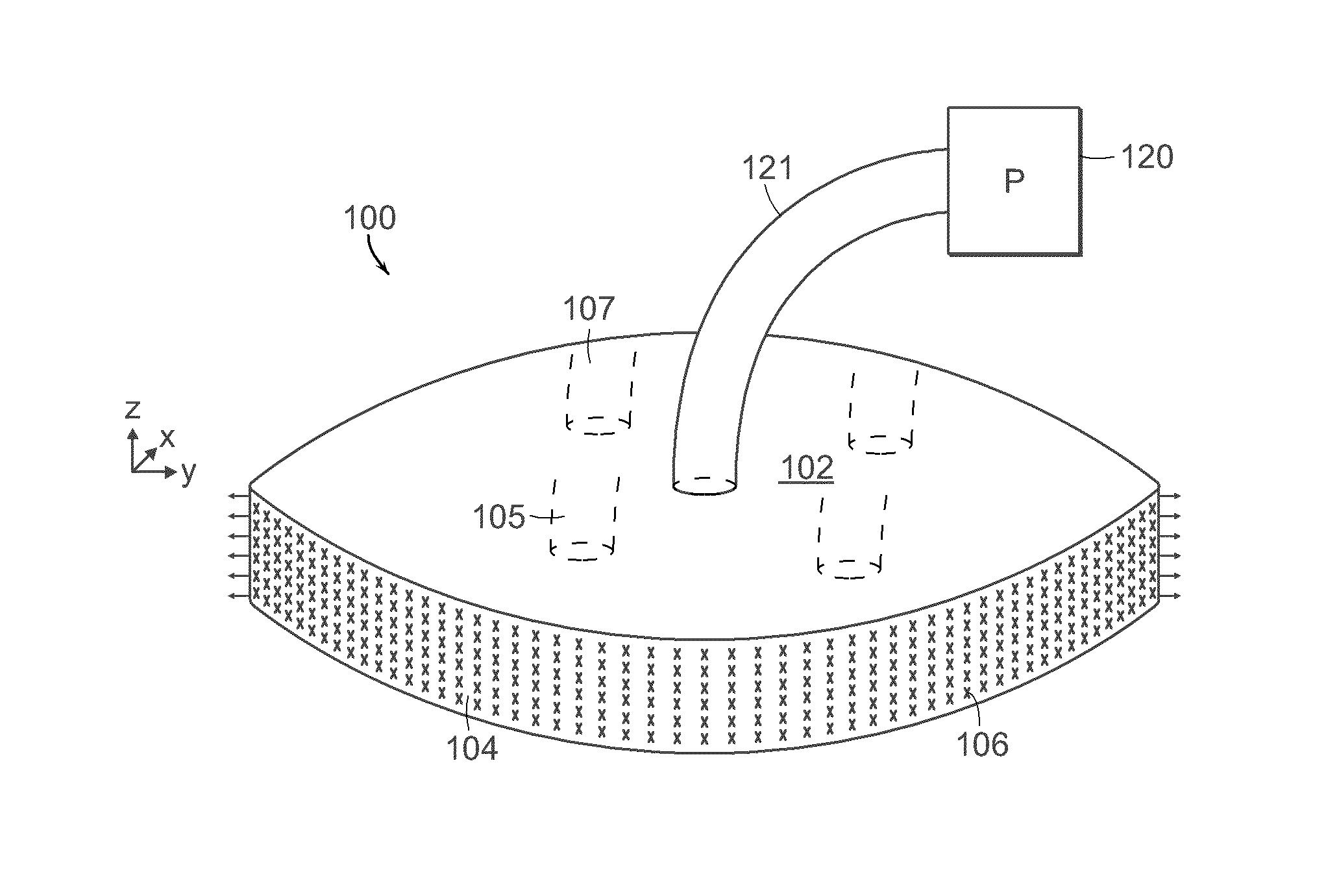
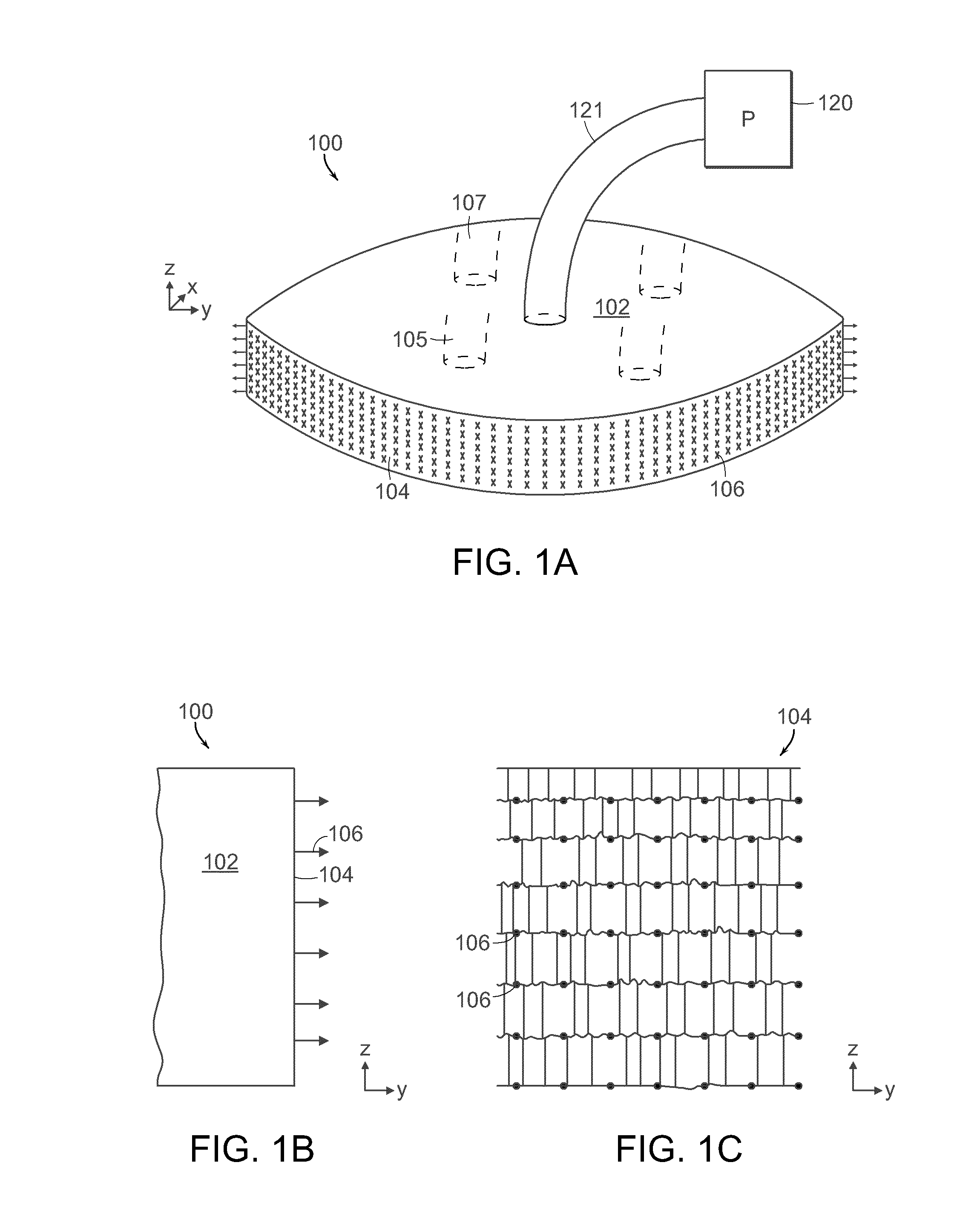
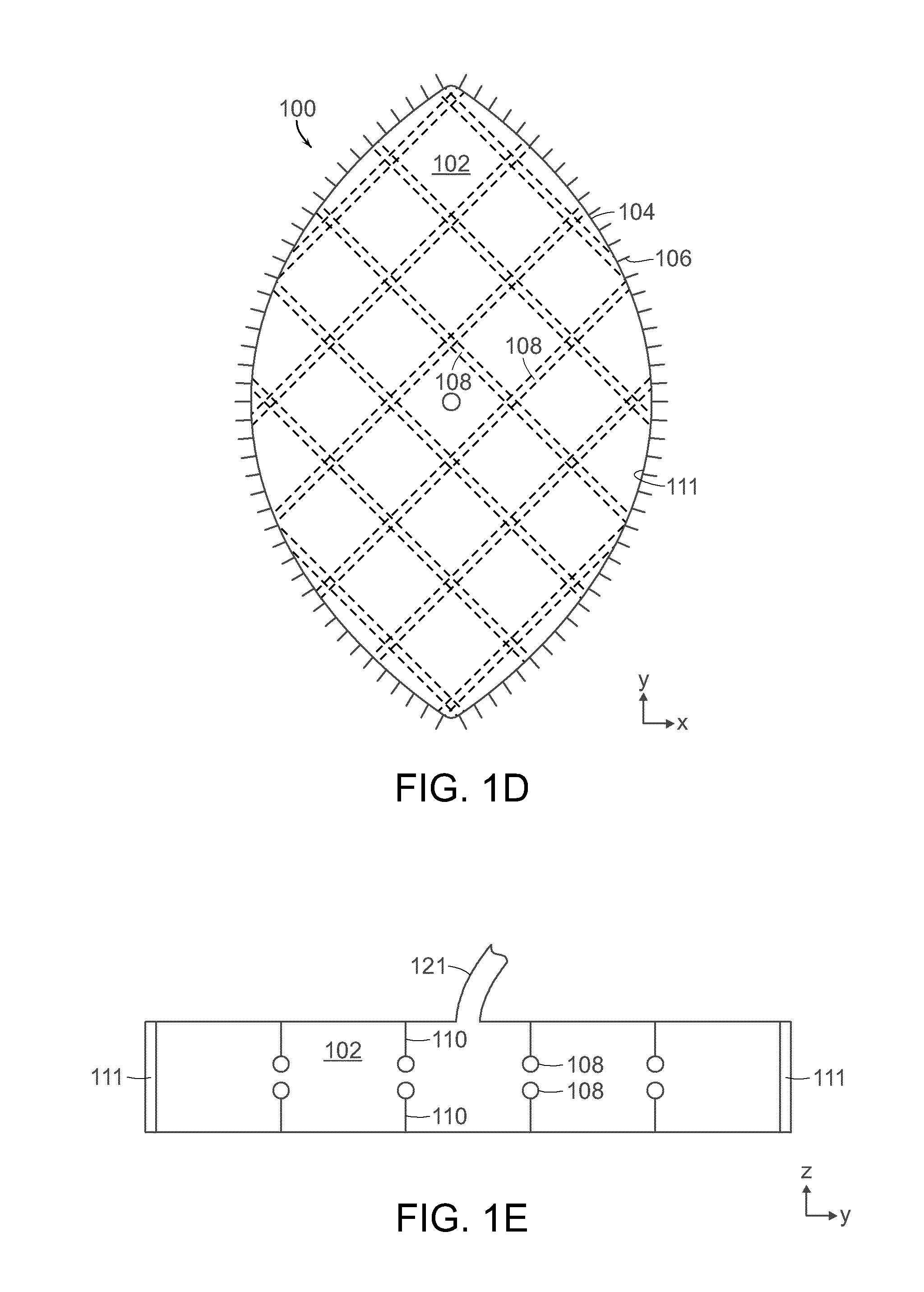
[0057]FIGS. 1A-1F illustrate an embodiment of a wound closure device 100 of the present invention. The device 100 includes a wound filler material 102 that is sized and shaped to fit within a wound opening of a human or animal patient. In preferred embodiments, the filler material 102 is a porous, biocompatible material, such as an open cell polyurethane foam. The filler material 102 is also preferentially collapsible, meaning that its size can be reduced along at least one dimension (e.g., length, width, height) by applying a negative pressure to the filler material 102, while at the same time inhibiting contractions or contracting at a slower rate in another direction. Further details regarding devices and methods of the present invention can be found in U.S. application Ser. No. 13 / 365,615 filed on Feb. 3, 2012, the entire contents of which is incorporated herein by reference.

[0058]Extending over at least one surface of the filler material 102, and preferably extending over an ou...


PUM


Abstract

The present invention relates to a negative pressure wound closure system and methods for using such a system. Preferred embodiments of the invention facilitate closure of the wound by preferentially contracting to provide for movement of the tissue. Preferred embodiments can utilize tissue grasping elements to apply a wound closing force to the tissue.

Description

CROSS REFERENCE TO RELATED APPLICATIONS[0001]This application is a continuation-in-part of U.S. application Ser. No. 13 / 365,615, filed Feb. 3, 2012, which claims the benefit of U.S. Application Nos. 61 / 439,525, filed Feb. 4, 2011. This application also claims the benefit of U.S. Application No. 61 / 672,173 filed Jul. 16, 2012, U.S. Application No. 61 / 679,982 filed Aug. 6, 2012, and U.S. Application No. 61 / 779,900, filed Mar. 13, 2013. The entire contents of the above applications are incorporated herein by reference.BACKGROUND OF THE INVENTION[0002]A number of techniques have been developed for treatment of wounds, including wounds resulting from accident and wounds resulting from surgery. Often, wounds are closed using sutures or staples. However, inserting these mechanical closure techniques requires making additional punctures or wounds to the skin, which can result in tissue injury and in the case of excess swelling, possible ischemia and tissue loss. Also, mechanical wound closu...

Claims


Application Information

Patent Timeline
Patent Type & Authority Patents(United States)
IPC IPC(8): A61M1/00A61F13/00A61B17/08
CPCA61M1/0088A61F13/00068A61B17/08A61B2017/081A61F2013/00174A61F2013/00536A61F2013/0054A61F2013/00544A61F2013/00548A61M1/96A61M1/915A61M1/916A61M2205/332A61M2205/3344A61M2205/50A61M2205/502A61M2210/1021
Inventor DUNN, RAYMOND
Owner UNIV OF MASSACHUSETTS
Why Eureka
Try Eureka