Rope terminal assembly and an elevator

a technology of elevator terminals and cables, which is applied in the direction of elevators, vehicles/pulleys, textile cables, etc., can solve the problems of difficult to make mechanical attachments with elevator units without causing damage, high weight and large thickness, and laborious and slow installation process, so as to improve the quality of installation and speed up the installation process , the effect of cost-effectiveness

Active Publication Date: 2016-08-23
KONE CORP
View PDF38 Cites 19 Cited by
  • Summary
  • Abstract
  • Description
  • Claims
  • Application Information

AI Technical Summary

Benefits of technology

[0006]The object of the invention is to introduce an improved rope terminal assembly and an elevator. The object of the invention is, inter alia, to solve drawbacks of known solutions and problems discussed later in the description of the invention. It is also an object to allow a cost-effective and reliable rope terminal assembly with faster installation process. The object of the invention is to provide rope terminal assembly with improved quality of installation for the elevator rope comprising polymer composite materials.
[0007]Embodiments are presented which, inter alia, facilitate simple, safe and efficient rope terminal assembly with connection to damage detection of non-metallic load bearing parts in said elevator ropes. Also, embodiments are presented, where rope terminal assembly enables rope condition monitoring where good and safe working position and good ergonomics can be ensured. Also, embodiments are presented, where reliable in situ condition monitoring of the ropes throughout the elevator life is possible.
[0009]Hence also safety of the rope terminal assembly is improved. Said rope end block is used as safety means for the rope terminal assembly. If the elevator rope slips in the rope gap of said rope terminal assembly, the rope end block pushes the wedge element such that the wedge element is arranged to wedge more tightly between said rope and said wedge housing thus locking said elevator rope in the gap.
[0011]In a preferred embodiment the rope terminal assembly is used in elevators with counterweight, however as well being applicable in elevators without counterweight. In addition, it can also be used in conjunction with other hoisting machines, e.g. as a crane suspension and / or transmission rope. The low weight of the rope provides an advantage especially in acceleration situations, because the energy required by changes in the speed of the rope depends on its mass. The low weight further provides an advantage in rope systems requiring separate compensating ropes, because the need for compensating ropes is reduced or eliminated altogether. The low weight also allows easier handling of the ropes.
[0015]Preferably rope end block is manufactured from plastics or some other electrically non-conductive material. Preferably rope end block is a single piece structure manufactured from plastics, preferably from thermoplastics polymer, for instance polyethylene, polypropylene, polystyrene or polyvinyl chloride, or thermosetting polymer, for instance polyester, polyurethanes or epoxy resins. The rope end block may be reinforced by glass, carbon or aramid fibers, and the reinforcing fibers may by short cut or they may be continuous fibers. Hence the mechanical properties, particularly specific strength and stiffness of the rope end block 3 are improved. The rope end block is preferably manufactured by extrusion, pultrusion, injection molding, blow molding, thermoforming, rotational molding, casting, foaming, compression molding or transfer molding, for instance. Thus the manufacturing of rope end block pieces is fast and the manufacturing costs are lower. Said rope end block pieces may also be manufactured from re-cycled plastics or other re-cycled materials.
[0023]In a preferred embodiment of the rope terminal assembly of an elevator the light-weight rope comprises one or more, preferably at least four unidirectional carbon fiber-reinforced-polymer load-bearing parts covered with polyurethane coating. In case of four load-bearing parts, the rope is electrically modeled as four resistors. Preferred solution is to measure one rope as a single resistance. In that way measuring arrangements are kept simple and the method is also more reliable, because the number of wires and connections is minimized. With this method simple and reliable solutions to short-circuit carbon fiber-reinforced-polymer load-bearing parts, and to connect the measuring wires to the rope, preferably by self-tapping screws screwed between the load-bearing parts in such a way, that the screw acts as an electrically conductive path between adjacent load-bearing parts, are used. At the counterweight end of said rope, preferably three screws are used to short-circuit all of the strands. At the car end of said rope, preferably two outermost load-bearing parts are connected together, and measuring wires are inserted under these two screws with a split ring connector. With this arrangement, all carbon fiber-reinforced-polymer load-bearing parts are monitored and the whole rope is seen as a single resistor.

Problems solved by technology

A problem with metallic ropes is, due to the material properties of metal, that they have high weight and large thickness in relation to their tensile stiffness and tensile strength.
With non-metallic elevator ropes, particularly with elevator ropes made of fiber-reinforced polymer composite materials, it is challenging to make mechanical attachment with the elevator unit without causing damage in the elevator rope.
Furthermore, installation process is laborious and slow.
Development of damage detection of fibre-reinforced polymer composite materials during service life is a key problem in many practical applications of elevator technology.
Many of these non-destructive tests involve the periodic inspection of composite components by means of costly equipment.

Method used


Image

  • Rope terminal assembly and an elevator
  • Rope terminal assembly and an elevator
  • Rope terminal assembly and an elevator

Examples


Embodiment Construction

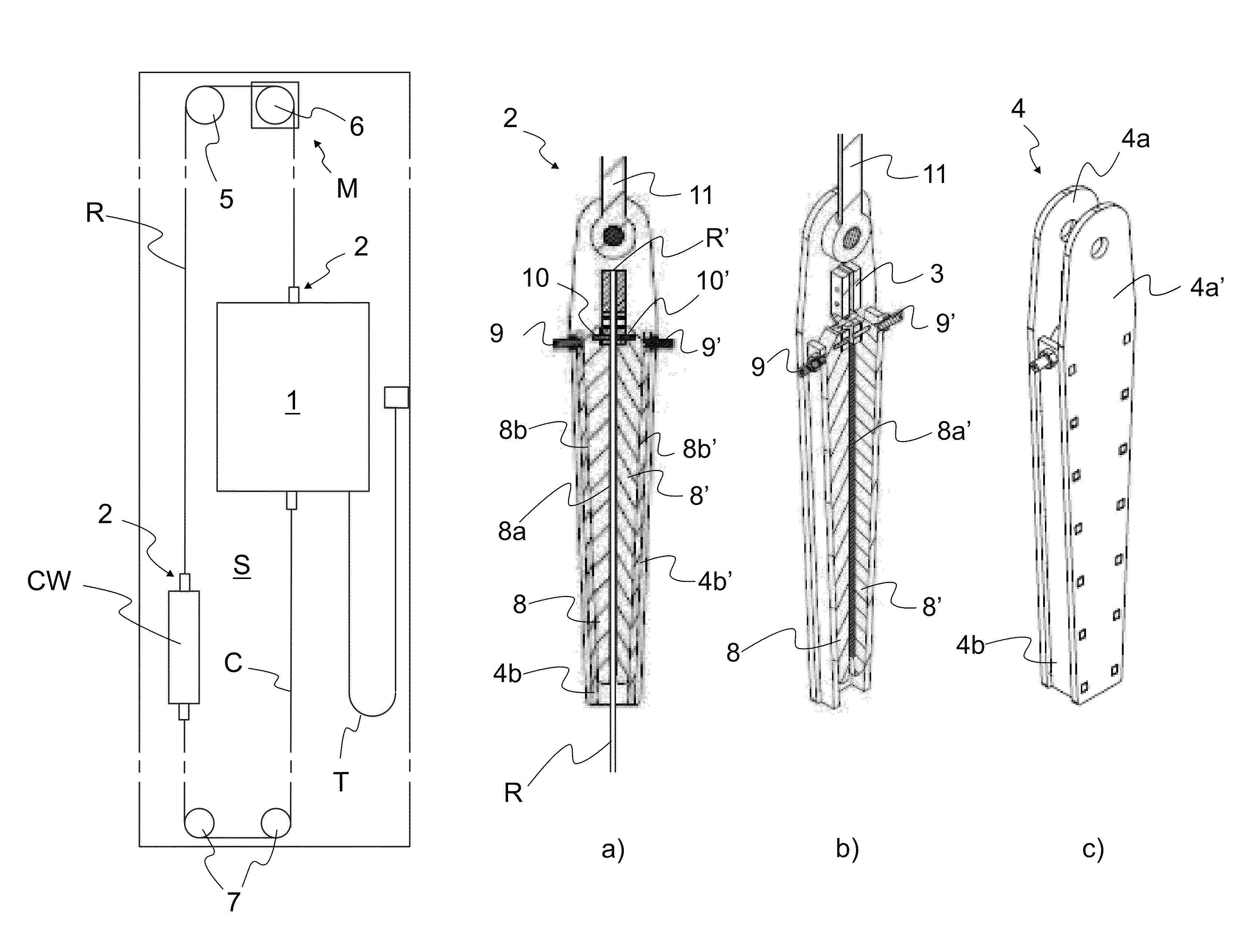
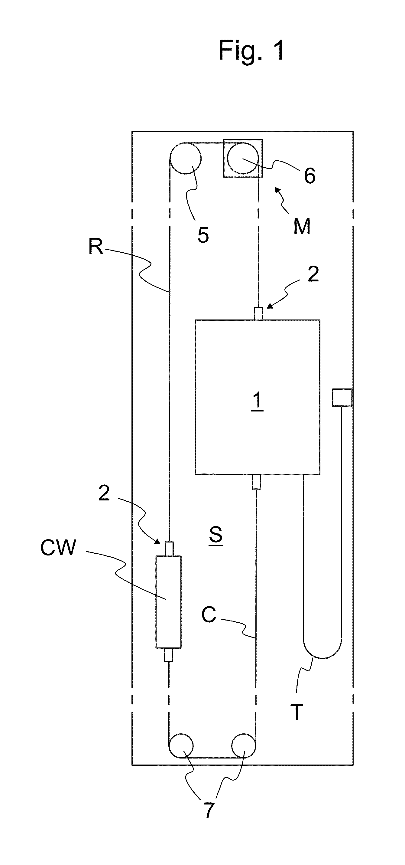
[0041]In FIG. 1 it is illustrated a preferred embodiment of an elevator where the elevator rope R, C is connected to the elevator unit 1, CW with a rope terminal assembly 2 according to the invention. The elevator has been arranged to comprise a hoistway S, and an elevator unit 1 movable in the hoistway S, the elevator unit being an elevator car 1 for transporting passengers and / or goods. The elevator arrangement may also comprise other movable elevator units such as the counterweight CW, as depicted. The elevator comprises lifting means comprising a lifting device M, roping comprising one or more suspension and transmission ropes R, each said rope R comprising one or more, preferably at least four load bearing parts 12a, 12b, 12c, 12d, attached with the rope terminal assembly 2 at least to one elevator unit 1, CW. Each rope R is guided to pass over the traction sheave 6 rotated by the hoisting machine M of the elevator and one ore more diverting pulleys 5. As the hoisting machine M...


PUM


Abstract

A rope terminal assembly of an elevator fixing an elevator rope to a fixing base such as an elevator unit, the elevator being suitable for transporting passengers and / or goods, includes an elevator rope, whose width is larger than its thickness in a rope transverse direction, with at least one end having an end face, a rope end block attached to the rope end, one or more wedge elements, a wedge housing, where the terminal assembly includes a rope gap through which the elevator rope passes and the wedge element is arranged to wedge between the rope and the wedge housing thus locking the elevator rope in the gap, and the rope end block is attached on the end face side of the elevator rope with respect to the wedge element, and an elevator.

Description

FIELD OF THE INVENTION[0001]The object of the invention is a rope terminal assembly of an elevator, the elevator being suitable for transporting passengers and / or goods, and an elevator.BACKGROUND OF THE INVENTION[0002]In elevator systems, elevator ropes are used for suspending and / or moving an elevator car, a counterweight or both. Elevator ropes are generally made by braiding from metallic wires or filaments and have a substantially round cross-sectional shape. A problem with metallic ropes is, due to the material properties of metal, that they have high weight and large thickness in relation to their tensile stiffness and tensile strength.[0003]Also light-weight suspension ropes, where the width of the suspension rope for a hoisting machine is larger than its thickness in a transverse direction of the rope, are known. The rope comprises a load-bearing part made of composite materials, which composite materials comprise non-metallic reinforcing fibers in polymer matrix material. T...

Claims


Application Information

Patent Timeline
Patent Type & Authority Patents(United States)
IPC IPC(8): B66B7/08B66B5/00F16G11/04B66B7/06B66B7/12
CPCB66B5/0031B66B5/0025B66B7/085F16G11/04B66B5/0018F16G11/042F16G11/048B66B7/062B66B7/1223
Inventor IKONEN, ANTTILUOMA, JANIHALLIKAINEN, PEKKAPELTO-HUIKKO, RAIMO
Owner KONE CORP
Why Eureka
Try Eureka