Flow cell, analysis equipment and analysis method using same

a flow cell and flow technology, applied in the field of flow cells, can solve the problems of difficult identification of the same bio-related substance, irregular position of bio-related substances, and difficulty in control

Active Publication Date: 2016-08-30
HITACHI HIGH-TECH CORP
View PDF2 Cites 12 Cited by
  • Summary
  • Abstract
  • Description
  • Claims
  • Application Information

AI Technical Summary

Benefits of technology

[0022]A solution containing the bio-related substance, such as a cell or a bacterium, can be sent to a device, placed at single and independent positions, and analyzed. Problems, configurations, and effects other than those mentioned above will become apparent from the following

Problems solved by technology

Further, because the method using external force is difficult to control, it may be most desirable to use a bio-related substance placing method based solely on fluid dynamics.
However, in the above method, except for the case where the bio-related substances are nonspecifically adsorbed on the slide glass or the cover glass and the like, the position of the bio-related substances are irregularly changed by Brownian motion or the motility of the bio-related substances themselves, for example.
Thus, once the bio-related substance is out of the observation field of view, it is difficult to identify the same bio-related substance again.
Further, because the intervals of the bio-related substances are average values after all, the bio-related substances are not always present at the independent positions and may be adjacent to another bio-related substance (in this case, the analysis device cannot determine that the bio-related substances are adjacent to each other).
Another problem is that it is difficult to follow the movement of the bio-related substances.
However, when the size is small such as on the order of several μm, as in the case of, e.g., bacteria, the application may become more difficult if the shape is not spherical but bar-like and the substances themselves have motility.
When the gap between the microwells and the cover glass is filled with liquid, the bacteria having motility may possibly flow out.
Further, in order to replace the solution in the microwells, large amounts of fluid and time are required due to poor substitution efficiency, making recovery of the bio-related substances difficult.
If the basket-shaped trapping structural member does not have the slits, it becomes difficult to flush out air (air bubbles) present before the solution is sent, which is not practical.
Because the value of the slit width design value to which a maximum process error of the slit is added must be smaller than the size of the bio-related substance, a high process accuracy on the order of 0.1 μm is required, resulting in an increase in manufacturing cost.
The second problem is that, while the probability of a plurality of bio-related substances being trapped by the same trapping structural member is lowered by making the size of the trapping structural member similar to that of the bio-related substance so that single bio-related substances can be trapped in most of the trapping structural members, when the size or shape of the bio-related substance is diverse, a plurality of bio-related substances may be trapped in one trapping structural member.
The third problem is that, because not all of the bio-related substances can be trapped by the trapping structural member and only the trapped bio-related substances are used as the object for analysis, important information may be missed, or the number of the bio-related substances cannot be quantified.
The fourth problem is that, as the bio-related substance is continuously subjected to the force pulling it into the slit portion, stress may be caused in the bio-related substance, possibly resulting in a change in phenotype.
However, there are the following problems.
The second problem is that not all of the bio-related substances can be trapped by the trapping structural member, and no analysis of the conditions is conducted.
The third problem is that, as the bio-related substance is continuously subjected to the force pulling it toward the slit portion, stress may be caused in the bio-related substance, possibly resulting in a change in phenotype.
The fourth problem is that, as discussed in Non Patent Literature 3, when the solution is sent at high speed, the bacteria may possibly be dissolved.

Method used


Image

  • Flow cell, analysis equipment and analysis method using same
  • Flow cell, analysis equipment and analysis method using same
  • Flow cell, analysis equipment and analysis method using same

Examples


Embodiment Construction

[0051]In the following, embodiments of the present invention will be described with reference to the drawings. The present invention can be generally applied to an analysis device of a system such that a plurality of bio-related substances are placed at single and independent positions for analysis. In the following, an example in which the present invention is applied to a bacterial analysis will be described.

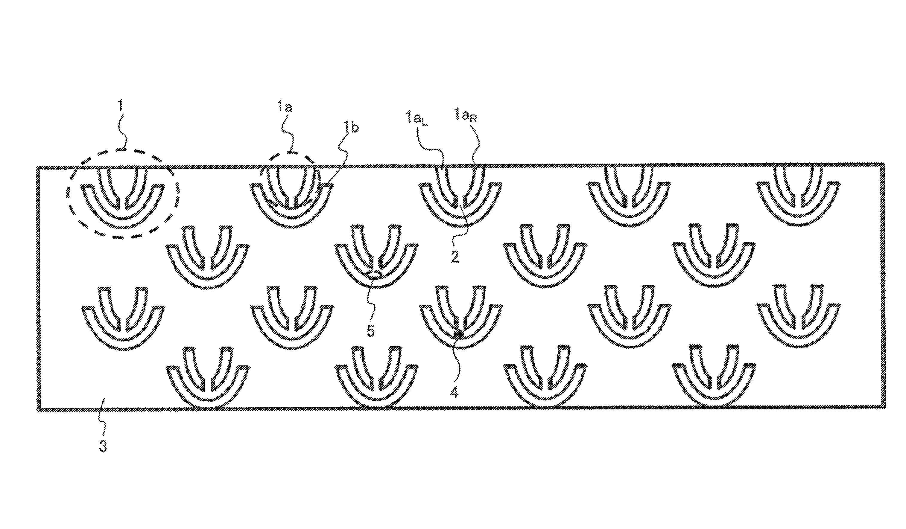
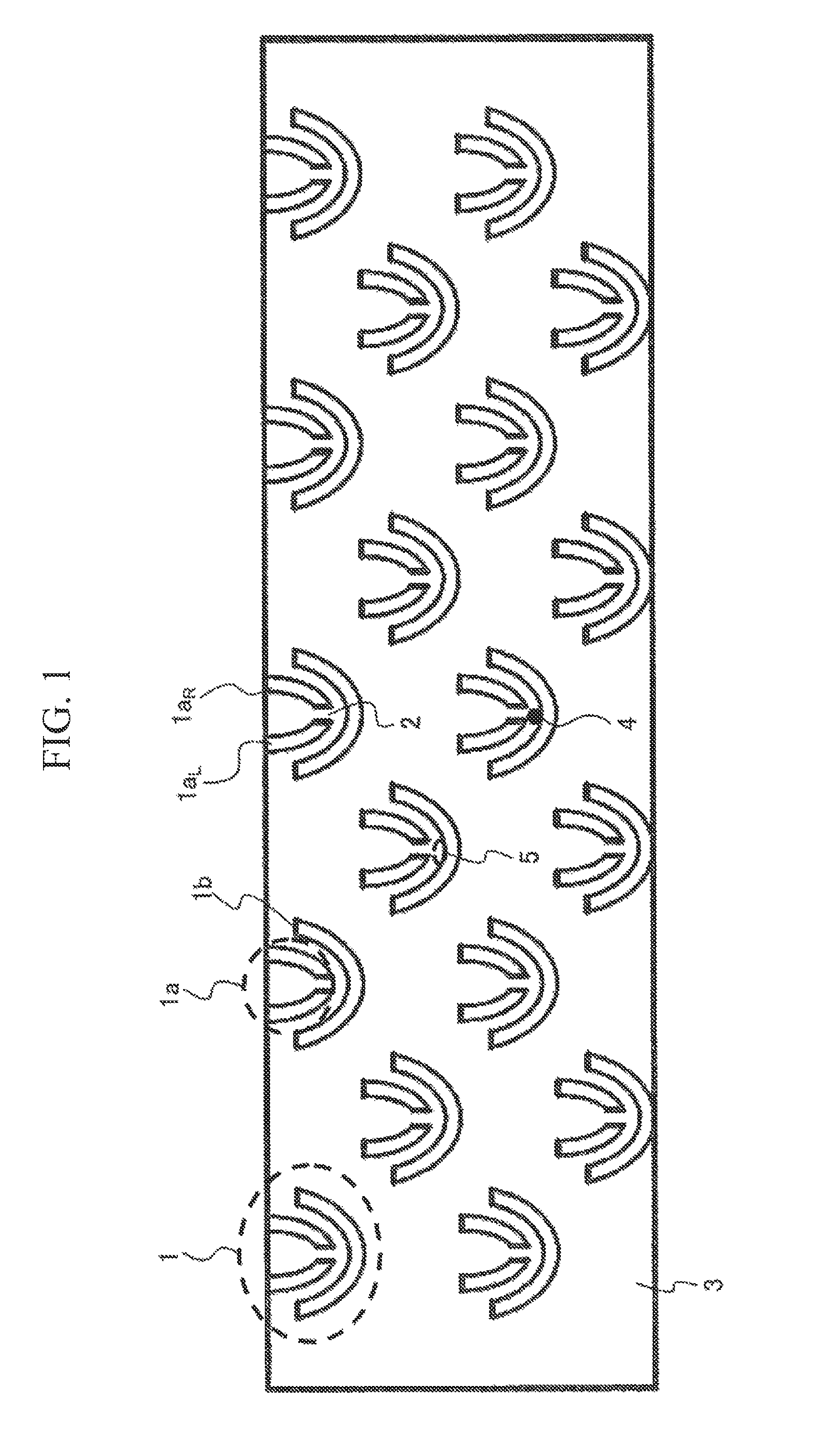
[0052]FIG. 1 is a schematic diagram of an example of trapping structural members according to the present invention. The trapping structural members 1 are structural members including a pair of a structural member 1a with a slit and a structural member 1b without a slit, and a plurality of the trapping structural members 1 are disposed. The structural member 1a with a slit includes a left side 1aL, of the structural member with a slit and a right side 1aR of the structural member with a slit, with a slit 2 disposed between the sides. A solution (not shown) containing bio-relat...


PUM

PropertyMeasurementUnit
sizeaaaaaaaaaa
lengthsaaaaaaaaaa
lengthsaaaaaaaaaa

Abstract

All of bio-related substances, such as cells or bacteria, are placed at single and independent positions. A flow cell according to the present invention is used for analyzing a bio-related substance and includes a flow passageway and an injection opening and a discharge opening that are connected to the flow passageway. The flow passageway is provided with trapping structural members for trapping the bio-related substance. The trapping structural members include a structure forming a dead water region in which the bio-related substance is trapped.

Description

TECHNICAL FIELD[0001]The present invention relates to a flow cell for performing analysis by sending a solution containing bio-related substances, such as cells or bacteria, to a device, and placing all of the substances at single and independent positions, an analysis device using the same, and an analysis method.BACKGROUND ART[0002]Generally, analysis of a bio-related substance, such as cells or bacteria, is conducted by a technique whereby the bio-related substance is multiplied by culturing, and then an average value of a number of bio-related substances is determined. Meanwhile, a method for analyzing single bio-related substances has been proposed in recent years, and researches on cell response or suppression mechanism, cell-cell interaction, and stem cell differentiation are being conducted. As a result, it has been established that an averaged behavior of a number of bio-related substances greatly differs from the behavior of single bio-related substances. In this method, a...

Claims


Application Information

Patent Timeline
Patent Type & Authority Patents(United States)
IPC IPC(8): G01N21/75G01N33/483B01L3/00C12M1/34C12M1/00G01N15/14G01N15/10
CPCG01N15/1404C12M41/36C12M47/02G01N33/4833B01L3/502753G01N2015/1415G01N2015/1006B01L2300/0816B01L2300/0877B01L2400/0487B01L2400/086
Inventor MATSUI, TAKUYAMAESHIMA, MUNEO
Owner HITACHI HIGH-TECH CORP
Why Eureka
Try Eureka