
Systems and methods for generating damped electromagnetically actuated planar motion for audio-frequency vibrations

a technology of electromagnetic actuation and planar motion, applied in the field of tactile transducers, can solve the problems of generating excess unwanted acoustic noise, overwhelming the output of the audio driver, and producing unwanted acoustic noise, etc., and achieve the effect of producing unwanted audio and/or distortion

Active Publication Date: 2016-08-30
TACTION TECH
View PDF15 Cites 17 Cited by
  • Summary
  • Abstract
  • Description
  • Claims
  • Application Information

AI Technical Summary

Benefits of technology

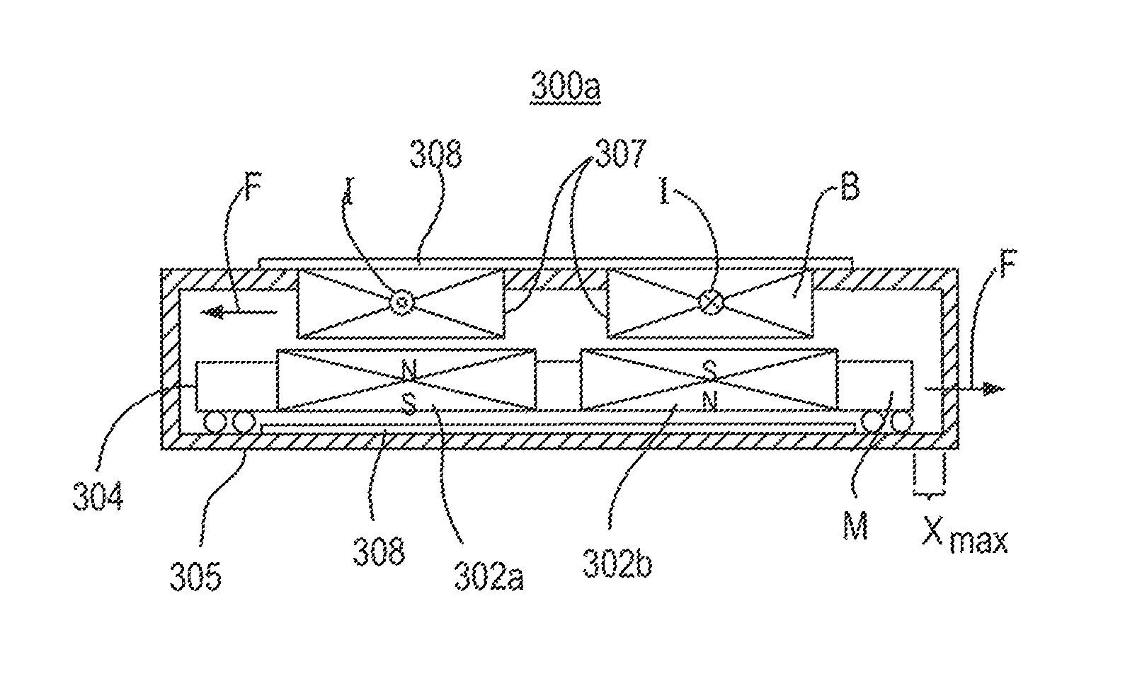
[0018]In some embodiments, proposed herein is a thin, flat vibration module with a movable member that is electromagnetically actuated to produce motion in-plane. Motion of the movable member can be damped so that the steady-state sinusoidal voltages applied to the module at different frequencies produce an acceleration response of the movable member that is substantially uniform over the range of 40-200 Hz. The module can be mounted in a headphone so that the motion axis lies substantially parallel to the sagittal plane of the wearer's head, so that the motion does not plunge the ear cup toward the wearer's ear canal, which produces unwanted audio and / or distortions.

Problems solved by technology

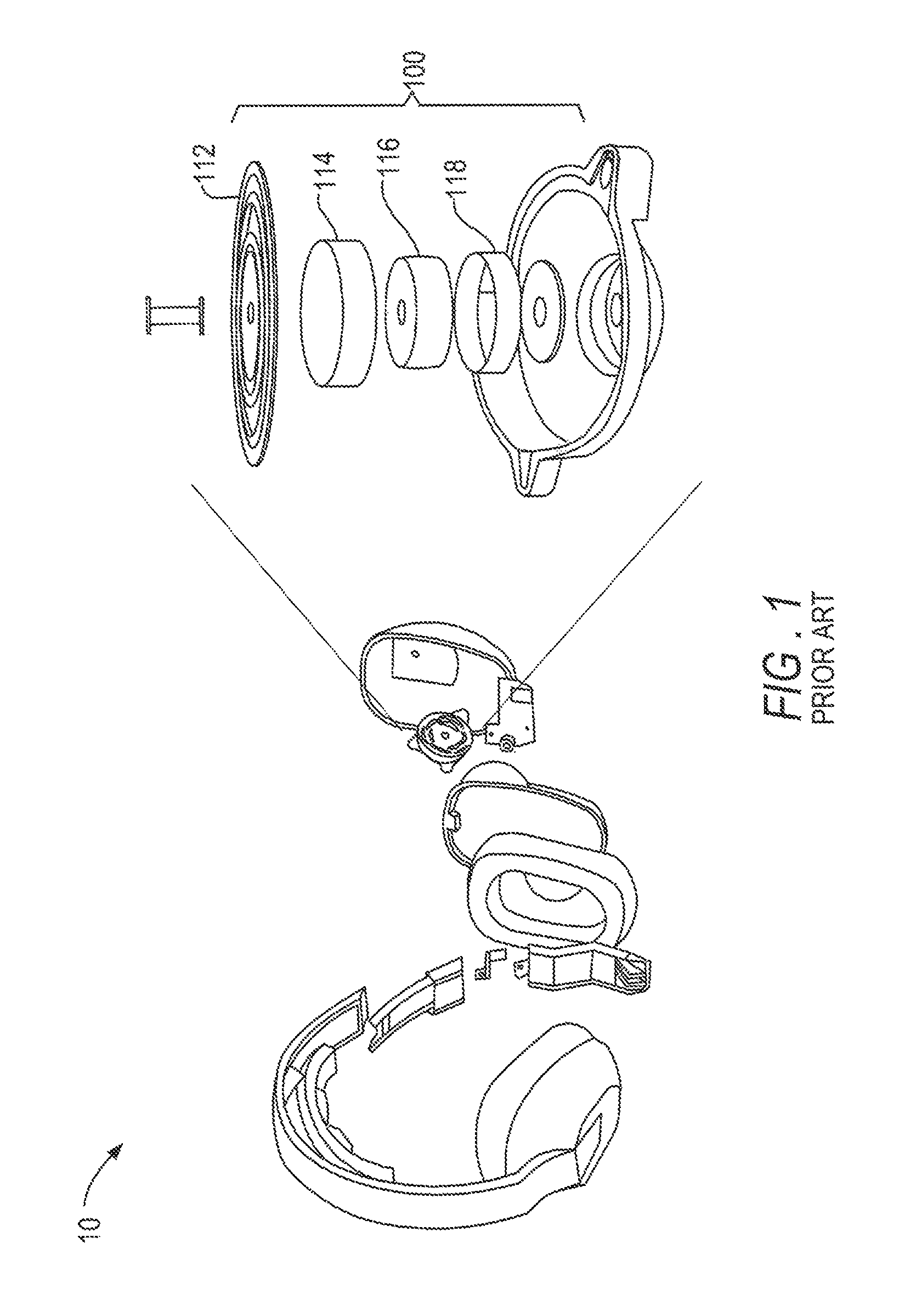
A drawback of this construction is the production of unwanted acoustic noise.
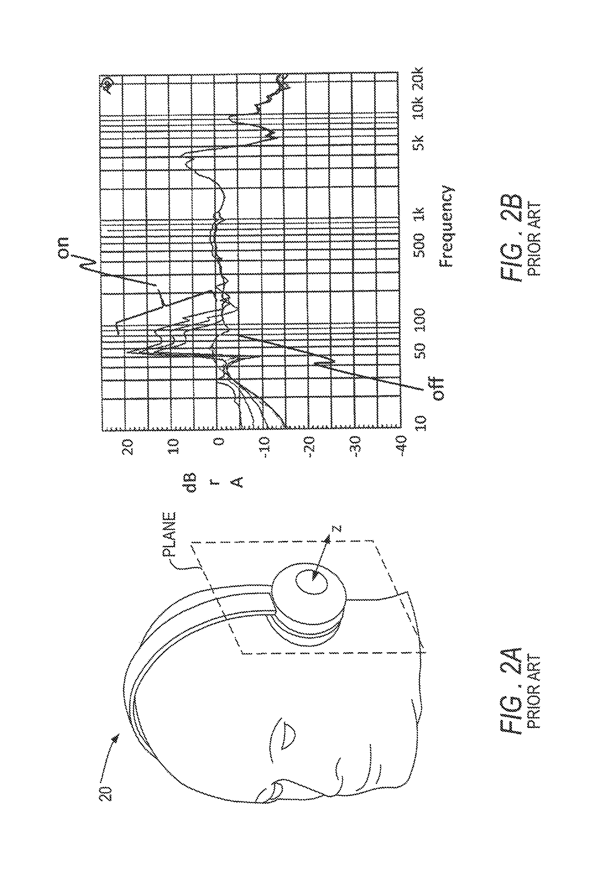
Thus, the same force that stimulates the skin under the ear cup cushions unfortunately also plunges air into the listener's ear canal, overwhelming the output of the audio driver and generating the excess unwanted acoustic noise.
In this example, significant audio is added to the acoustic frequency response, causing an undesirable bump of 10-20 dB in the 50-100 Hz range.
The result is a bass-heavy sound in which upper frequencies are underrepresented, and the user's perception is one of muffled, muddy sound.
The problem of uneven frequency response is typically made worse by a lack of mechanical damping.
Another approach in the prior art, also problematic, is the use of un-damped eccentric rotating motors (“ERMs”) and un-damped linear resonant actuators (“LRAs”).
Small, un-damped ERMs are incompatible with high-fidelity audio for a few reasons.
This linkage is fundamentally incompatible with acoustic fidelity.
The main drawback of LRAs is the dependence on the “resonance,” that the name suggests.
Such a high Q-factor renders this sort of device useless for high fidelity reproduction of low frequency tactile effects in the 15-120 Hz range.
In addition to the limited frequency range of LRAs there is a another problem with using LRAs as audio-frequency tactile transducers is that a transducer mounted vertically between the headphone bow and the top of the skull flexes the bow.
The inward-outward component of the flapping plunges the ear cups against the sides of the wearer's head, again producing undesirable audio that competes with and distorts the acoustic response of the audio drivers in the ear cups.
Although this in-plane approach has been contemplated, the dielectric elastomer actuators proposed for this purpose are expensive and complex devices that require high voltage electronics.
Another drawback of this approach was that no provision was made for critically damping those transducers.
A drawback of this guiding approach is the vulnerability of flexures to buckling when loaded by longitudinal compression.
This thickness comes at the expense of increased stiffness in the motion direction, which may undesirably impede movement.
Supporting the load with an elastic element has some undesirable drawbacks, however.

Method used


Image

  • Systems and methods for generating damped electromagnetically actuated planar motion for audio-frequency vibrations
  • Systems and methods for generating damped electromagnetically actuated planar motion for audio-frequency vibrations
  • Systems and methods for generating damped electromagnetically actuated planar motion for audio-frequency vibrations

Examples


Embodiment Construction

[0064]Various embodiments for providing damped electromagnetically actuated planar motion for audio-frequency vibrations are disclosed herein. The force output across a frequency range of a tactile transducer used for this purpose is limited by the space available for moving the internal mass and the peak force of the actuator causing the movement. FIG. 3A shows chart 30 illustrating these two physical bounds on the force output of an electromagnetic vibration module arising from limitations on the space available for translating the mass and from the limited force output of the coil. For an electromagnetic actuator, these limits may be termed travel limit 31 and coil limit 32, respectively. If the system is not underdamped, the output of the transducer can be described by a curve in region 33, below these limits 31 and 32.

[0065]The travel limit obeys the equation:

Fmax=mxmax(2πf)2  (1)

where:[0066]Fmax=[N], maximum force[0067]xmax=[m], space in package available for displacement[0068...


PUM


Abstract

A vibration module for applying vibrational tractions to a wearer's skin is presented. Use of the vibration module in headphones is illustrated for providing tactile sensations of low frequency for music, for massage, and for electrical recording and stimulation of the wearer. Damped, planar, electromagnetically-actuated vibration modules of the moving magnet type are presented in theory and reduced to practice, and shown to provide a substantially uniform frequency response over the range 40-200 Hz with a minimum of unwanted audio.

Description

CROSS-REFERENCE TO RELATED APPLICATIONS[0001]This application claims the benefit of U.S. Provisional Patent Application Ser. No. 62 / 054,712, entitled “DAMPED ELECTROMAGNETICALLY ACTUATED PLANAR MOTION FOR AUDIO-FREQUENCY VIBRATIONS,” filed Sep. 24, 2014, and U.S. Provisional Patent Application Ser. No. 62 / 101,985, entitled “SYSTEMS AND METHODS FOR PROVIDING DAMPED ELECTROMAGNETICALLY ACTUATED PLANAR MOTION FOR AUDIO-FREQUENCY VIBRATIONS,” filed Jan. 10, 2015, each of which is incorporated by reference herein in its entirety.FIELD OF THE INVENTION[0002]The present invention relates to tactile transducers that produce bass frequency vibrations for perception by touch.BACKGROUND OF THE INVENTION[0003]Below about 200 Hz, the lower the frequency of sound, the more it is perceived not only by vibration of the ear drum but also by touch receptors in the skin. This sensation is familiar to anyone who has “felt the beat” of strong dance music in the chest, or through the seat of a chair, or ...

Claims


Application Information

Patent Timeline
Patent Type & Authority Patents(United States)
IPC IPC(8): H04R1/00G08B6/00H04R1/10F16F7/10F16F15/03A61H23/00
CPCG08B6/00H04R1/1091F16F7/1011F16F15/03A61H23/00H04R5/0335H04R9/066H04R2460/13H04R1/1008H04R1/1075H04R5/033H04R2400/03A61H23/004A61B5/6898A61H23/0218A61H23/0236A61B5/6815A61N1/0484A61N1/36014A61H2201/0165A61H2201/10A61H2201/1207A61H2201/1604A61H2201/165A61H2201/5002A61H2201/5005A61H2201/5007A61H2201/5097A61H2205/021A61H2205/022A61H2230/00A61H2230/08A61H2230/10A61H2230/65A61N1/0456A61B5/24A61B5/389A61B5/398A61N1/00A61F11/145A61H23/02B06B1/045F16F7/1034F16F9/02
Inventor BIGGS, SILMON JAMES
Owner TACTION TECH
Learn More