Image processing apparatus and image processing method

a technology of image processing and image data, applied in the direction of picture signal generators, solid-state device signal generators, television systems, etc., can solve the problems of affecting the quality of images, so as to reduce the noise in raw images

Active Publication Date: 2016-08-30
CANON KK
View PDF60 Cites 8 Cited by
  • Summary
  • Abstract
  • Description
  • Claims
  • Application Information

AI Technical Summary

Benefits of technology

[0010]The present invention provides an image processing apparatus and an image processing method capable of reducing noise in a RAW image.
[0012]The present invention accomplishes noise reduction even for image data, such as a RAW image, having signal values of different levels on a pixel basis according to color filters. Thus, high-quality image data can be generated from even image data captured by a digital image capturing device having any selected color filter array.

Problems solved by technology

In the process of generating digital image data, noise such as dark-current noise, thermal noise, and shot noise is generated by the characteristics of the image capturing element and circuit, and contaminates the digital image data.
The noise is generated markedly and is a strong factor in image degradation, especially in a case, for example, where ISO sensitivity is increased.
However, this method blurs not only the noise but also the edge, and therefore makes it difficult to obtain a high-quality image.
However, in a case of an image like a RAW image in which pixels have signal values of different levels depending on the color filter, there is a problem that noise cannot be reduced by simply setting the target area and the reference pixels.
On the other hand, in a case where the conventional methods are used on a color image generated from a RAW image, color image data needs to be generated by performing pixel interpolation and the like on RAW image data which still contains noise, which contributes to image quality degradation.

Method used


Image

  • Image processing apparatus and image processing method
  • Image processing apparatus and image processing method
  • Image processing apparatus and image processing method

Examples


embodiment 1

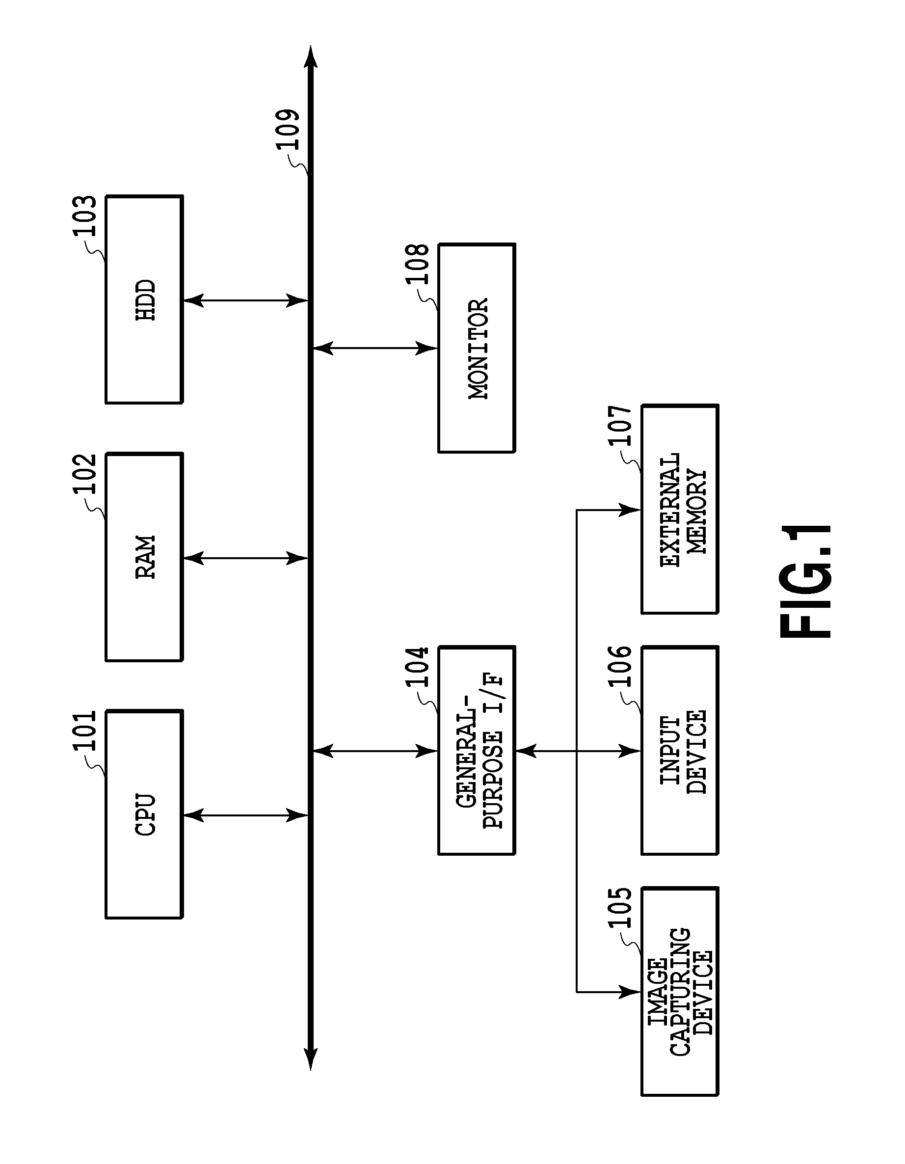
[0031]With reference to FIG. 1, the configuration of an image processing apparatus of this embodiment is described.

[0032]In FIG. 1, the image processing apparatus includes a CPU 101, a RAM 102, an HDD 103, a general-purpose interface (I / F) 104, a monitor 108, and a main bus 109. The general-purpose I / F 104 connects an image capturing device 105 such as a camera, an input device 106 such as a mouse and a keyboard, and an external memory 107 such as a memory card, to the main bus 109.

[0033]A description is given below of various kinds of processing implemented by the CPU 101 operating various types of software (computer programs) stored in the HDD 103.

[0034]First, the CPU 101 activates an image processing application stored in the HDD 103, deploys the application on the RAM 102, and displays a user interface (UI) on the monitor 108. Next, various types of data stored in the HDD 103 and the external memory 107, RAW image data captured by the image capturing device 105, commands from th...

embodiment 2

[0083]In Embodiment 1, the parameters are determined for each color in the color filter information. In the method of determining the parameters for each color, pixels of the same color as the target pixel serve as its reference pixels, and therefore the target area needs to be determined such that all the pixels of the same color therein coincide with those in each reference area. In a method described in this embodiment, not all the pixels of the same color in the target area need to coincide with those in the reference area, or in other words, reference pixels are determined such that they coincide with pixels in the target area. Specifically, in the example described in Embodiment 1, reference pixels are determined first, and then pixels to be used as a target area are determined such that they correspond to the reference pixels. In an example to be described in Embodiment 2, pixels to be used as a target area are determined first, and then reference pixels corresponding to the ...

embodiment 3

[0099]In the example described in Embodiment 2, the color filter information is a Bayer array. In a case where the color filters have high random nature, the reference pixels might become thin with respect to the target pixel, which could lower the noise reduction effect. This case of thin reference pixels is described with reference to FIG. 12. FIG. 12 shows an example of color filters having higher random nature than the Bayer array, and shows a target pixel in black and pixels used as a target area in gray. Black-edged pixels near the target pixel are pixels of the same color as the target pixel, namely red, but a target area cannot be determined uniformly by color as described in Embodiment 1. Also, Black-edged pixels are not selected as the reference pixel candidates in the method described in Embodiment 2 because the pixel placements constituted by them do not coincide with that of the target pixel. As a result, the number of reference pixels used for correction of the target ...


PUM


Abstract

Noise in RAW image data is reduced by determining parameters including pixels used as a target area and reference pixels in the RAW image data, based on color filter information for the RAW image data. The RAW image data is corrected based on the parameters thus determined.

Description

BACKGROUND OF THE INVENTION[0001]1. Field of the Invention[0002]The present invention relates to an image processing apparatus and an image processing method for reducing noise contained in image data.[0003]2. Description of the Related Art[0004]Digital still cameras and digital video cameras have come into widespread general use. These digital image capturing devices generate digital image data by converting, into digital signals, light received by a photoelectric conversion element (image capturing element), such as a CCD or CMOS sensor. To obtain image data representing a color image, color filters having different transmittances depending on the wavelength of light are arranged regularly in front of the image capturing element. A digital image capturing device generates color signals based on the difference among the amounts of light transmitted through the color filters. Thus, image data recorded by the digital image capturing device (hereinafter referred to as RAW image data) ...

Claims


Application Information

Patent Timeline
Patent Type & Authority Patents(United States)
IPC IPC(8): H04N5/357H04N9/04H04N5/217
CPCH04N5/357H04N9/045H04N5/2173H04N25/60H04N25/134
Inventor SASAKI, YOSHITAKAYAHATA, KAZUHIRO
Owner CANON KK
Why Eureka
Try Eureka