Fibre optic distributed sensing

a distributed sensing and fiber optic technology, applied in the field of fiber optic distributed sensing, can solve the problems of increasing the amount of processing required, affecting the sensitivity of the detector, and the sample rate of the detector is in excess of hundreds of mhz, and the detector bandwidth is also much higher

Active Publication Date: 2016-09-06
OPTASENSE HLDG LTD
View PDF21 Cites 17 Cited by
  • Summary
  • Abstract
  • Description
  • Claims
  • Application Information

AI Technical Summary

Benefits of technology

[0008]The present invention provides improved methods and apparatus for fibre optic distributed sensors, especially distributed acoustic sensors which mitigate at least some of the aforementioned disadvantages.

Problems solved by technology

However use of such a high carrier frequency would require detector sample rates in excess of hundreds of MHz.
This not only would require very fast components for the interrogator unit and greatly increase the amount of processing required but a much higher detector bandwidth would also impact on the sensitivity of the detector.

Method used


Image

  • Fibre optic distributed sensing
  • Fibre optic distributed sensing
  • Fibre optic distributed sensing

Examples


Embodiment Construction

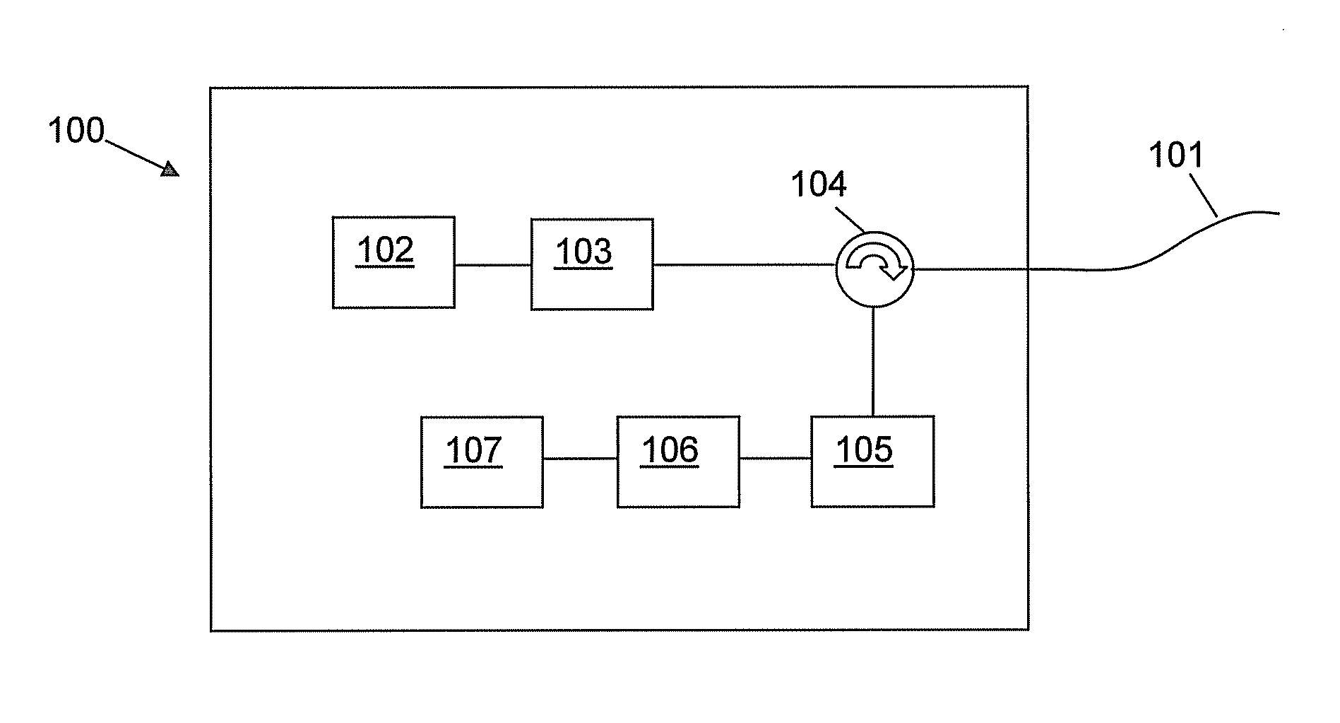
[0103]The general components of an interrogator unit of a distributed acoustic sensor are illustrated with respect to FIG. 1. In use the interrogator unit 100 is connected to an optical fibre 101 which acts as the sensing fibre. The sensing fibre is coupled to an output / input of the interrogator using conventional fibre optic coupling means. The interrogator unit is arranged to launch pulses of coherent optical radiation into the sensing fibre 101 and to detect any radiation from said pulses which is Rayleigh backscattered within the optical fibre. To generate the optical pulses the interrogator unit 100 comprises at least one laser 102. The output of the laser is received by an optical modulator which generates the pulse configuration as will be described later. The pulses output from the optical modulator 103 are then transmitted into the sensing fibre 101, for instance via a circulator 104.

[0104]Any optical radiation which is backscattered from said optical pulses propagating wit...


PUM


Abstract

The application describes methods and apparatus for distributed fiber sensing, especially distributed acoustic/strain sensing. The method involves launching interrogating radiation in to an optical fiber and sampling radiation backscattered from within said fiber at a rate so as to acquire a plurality of samples corresponding to each sensing portion of interest. The plurality of samples are divided into separate processing channels and processed to determine a phase value for that channel. A quality metric is then applied to the processed phase data and the data combined to provide an overall phase value for the sensing portion based on the quality metric. The quality metric may be a measure of the degree of similarity of the processed data from the channels. The interrogating radiation may comprise two relatively narrow pulses separated by a relatively wide gap and the sampling rate may be set such that a plurality of substantially independent diversity samples are acquired.

Description

FIELD OF THE INVENTION[0001]This invention relates to fibre optic distributed sensing and in particular to methods and apparatus for determining phase modulations on said fibre, and especially to fibre optic distributed acoustic sensing.BACKGROUND OF THE INVENTION[0002]Fibre optic distributed acoustic sensors are known. Such sensors interrogate optical fibres with optical radiation and measure changes to the radiation resulting from acoustic waves affecting the optical fibre.[0003]U.S. Pat. No. 5,194,847 (Texas A&M Univ) describes interrogating a fibre with a repeated coherent pulse of radiation and detecting any radiation which is Raleigh backscattered within the fibre. The fibre is interrogated with a single pulse at a time and the amplitude of the backscattered radiation is analysed to detect any disturbance of the fibre by acoustic / pressure waves. This document teaches that a buried optical fibre can be used as a distributed acoustic sensor for perimeter monitoring purposes.[000...

Claims


Application Information

Patent Timeline
Patent Type & Authority Patents(United States)
IPC IPC(8): G01D5/353G01D1/00G01D1/02
CPCG01D5/35358G01D1/00G01D1/02G01D5/3539G01D5/35345G01D5/35361G01D5/35367G01D5/35387G01D5/35393G01D5/35396G01D5/35303G01D5/35312G01D5/35329G01D5/35306G01H9/004G01D5/35383
Inventor LEWIS, ANDREW BIGGERSTAFFRUSSELL, STUART JOHN
Owner OPTASENSE HLDG LTD
Why Eureka
Try Eureka