
Integrated circuit (IC) test structure with monitor chain and test wires

a technology of integrated circuits and test structures, applied in the direction of basic electric elements, semiconductor/solid-state device testing/measurement, instruments, etc., can solve the problems of overestimating the failure rate and presenting significant manufacturing challenges with vias

Active Publication Date: 2016-09-06
GLOBALFOUNDRIES US INC
View PDF12 Cites 61 Cited by
  • Summary
  • Abstract
  • Description
  • Claims
  • Application Information

AI Technical Summary

Benefits of technology

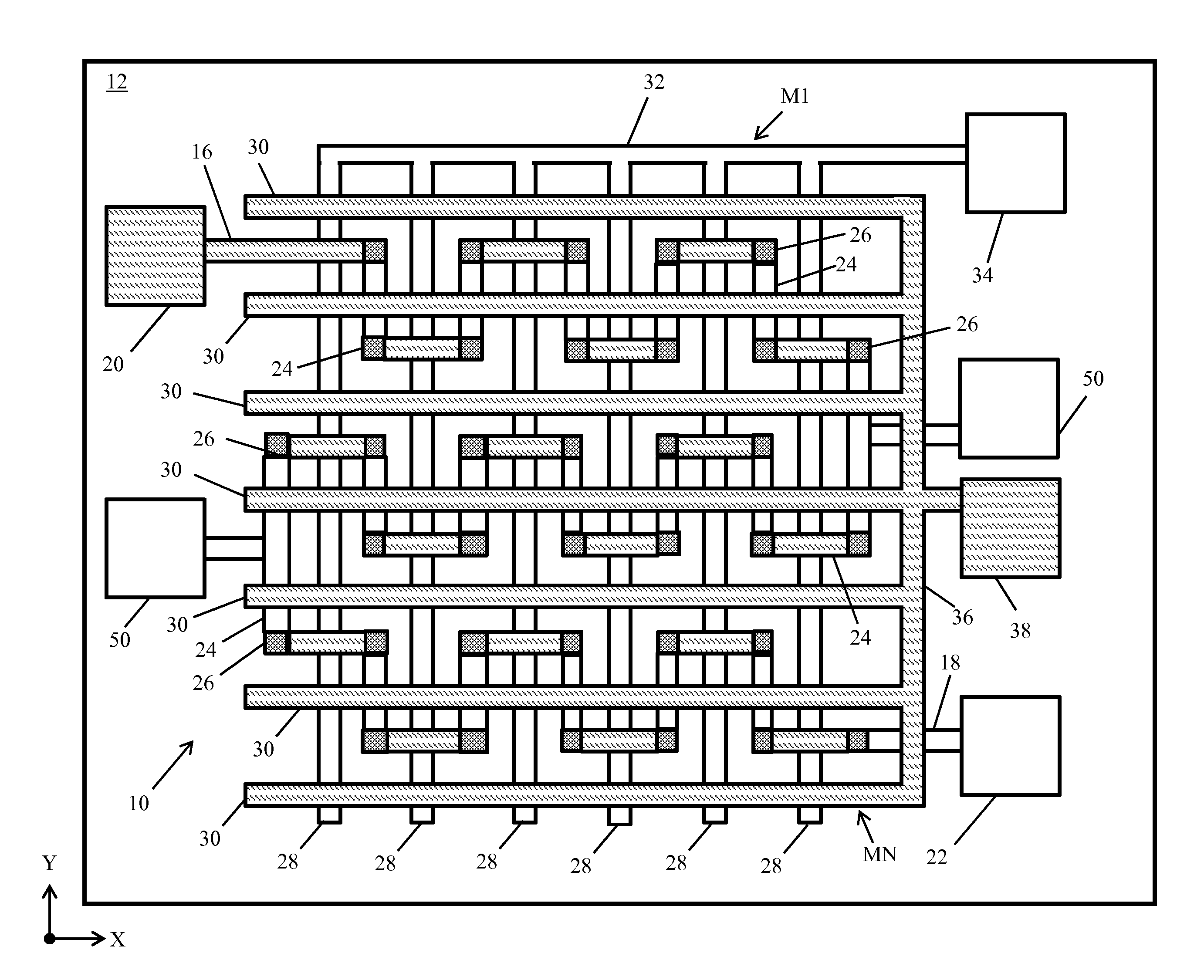
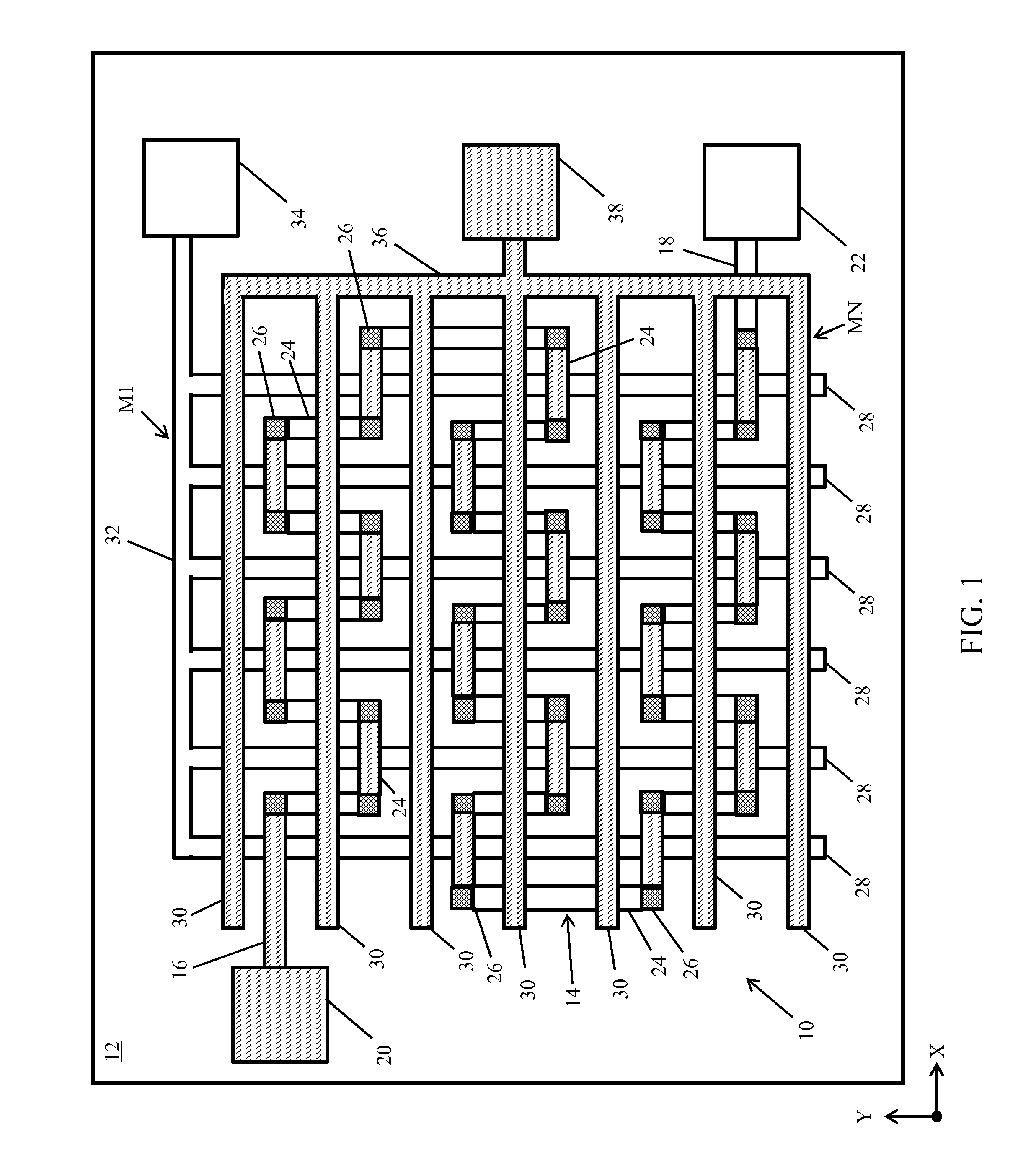
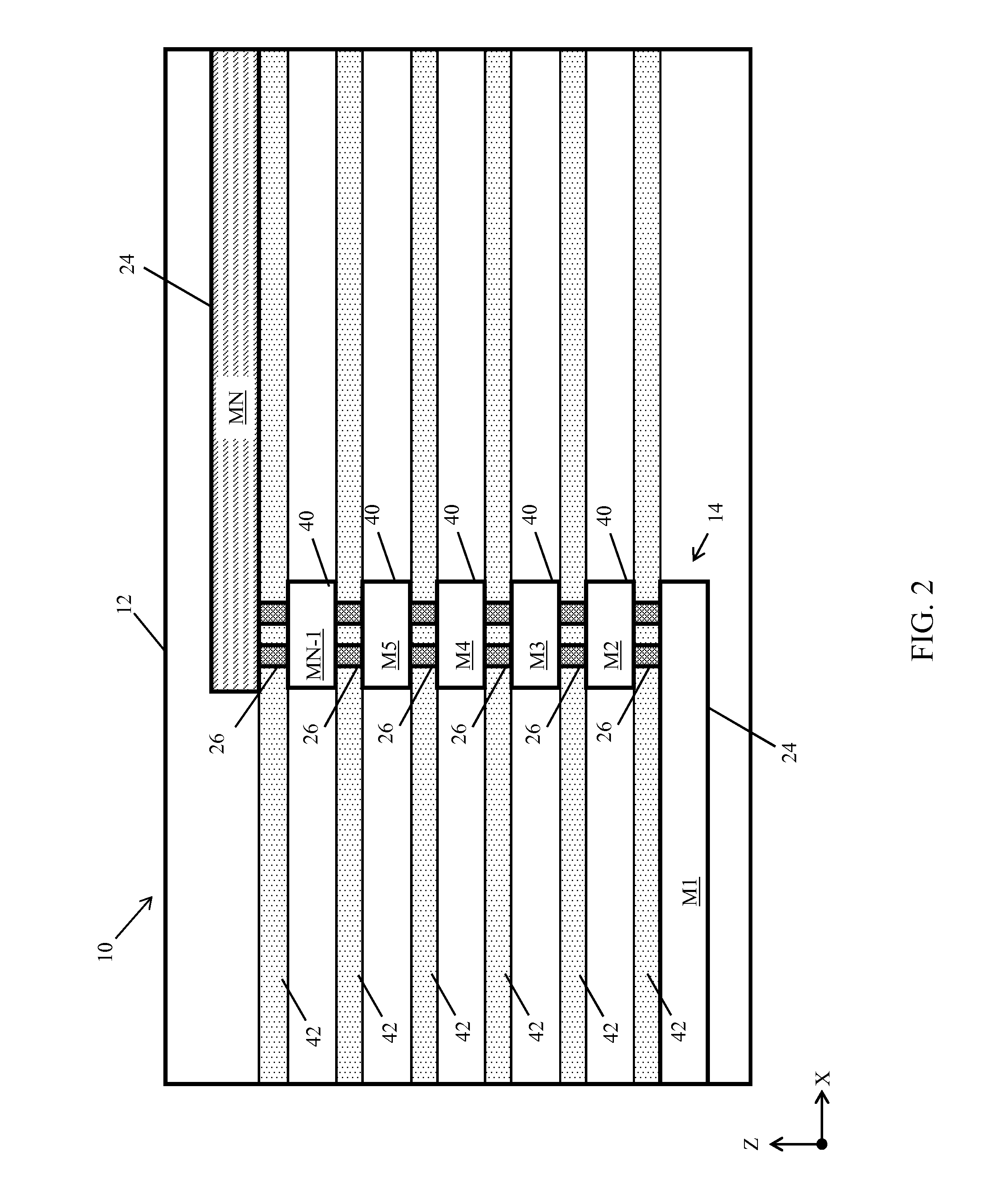
The present patent offers an IC test structure that can measure electrical shorts, opens, and other properties such as dielectric reliability, using multiple sources of testing through monitor chain, first test wire, and second test wire while reducing parasitic voltage drop. The test structure can also determine the location of an electrical short or structural fault within the IC chip. The testing can be performed using circuits providing boolean attributes, e.g., the presence or absence of breakdown in dielectric materials in particular regions or levels. The technical effect of the patent is to provide a more comprehensive and accurate method for testing IC chips.

Problems solved by technology

Vias can present a significant manufacturing challenge, because a single broken contact or electrical short can affect the operation of an entire product.
These types of test structures may be highly resistive and cause overestimations of failure rate because of the test current and “leakage” currents being of similar magnitude.
Alternative test structures may be more sensitive to changes in current, but may not test for a worst-case scenario due to differences in their underlying structure.

Method used


Image

  • Integrated circuit (IC) test structure with monitor chain and test wires
  • Integrated circuit (IC) test structure with monitor chain and test wires
  • Integrated circuit (IC) test structure with monitor chain and test wires

Examples


Embodiment Construction

[0014]Various aspects of the present disclosure can provide an integrated circuit (IC) test structure which offers sensitivity to errors or defects, along with an ability to test a wide array of test cases, e.g., whether via-to-via and / or via-to-wire faults are present. In an embodiment, an IC test structure according to the present disclosure can include, as one component, a monitor chain with a first end electrically connected to a second end through metal wires each positioned within a first or second metal level of the IC. As used herein, the term “monitor chain” generally refers to an electronic circuit composed of metal wires and vias positioned within two or more metal level layers, and which can be structured to include a serpentine structure. A monitor chain with a serpentine structure can include, e.g., sections which wrap laterally and / or vertically around other circuit elements, thereby providing a circuit which is proximal to and electrically isolated from other circuit...


PUM


Abstract

Aspects of the present disclosure provide an integrated circuit (IC) test structure. An IC structure according to the present disclosure can include: a monitor chain having a first end electrically connected to a second end through a plurality of metal wires each positioned within one of a first metal level and a second metal level, wherein the first metal level is vertically separated from the second metal level; a first test wire positioned within the first metal level and extending in a first direction, wherein the first test wire is electrically insulated from the monitor chain; and a second test wire positioned within the second metal level and extending in a second direction, wherein the second test wire is electrically insulated from the monitor chain and the first test wire, and wherein the first direction is different from the second direction.

Description

BACKGROUND[0001]The subject matter disclosed herein relates to methods and test structures for integrated circuits (ICs). More specifically, aspects of the invention relate to test and monitoring structures which can measure the reliability of an IC chip and its components, e.g., metal level layers and interlayer dielectrics therein.[0002]Each IC of a particular device can be made up of billions of interconnected devices, such as transistors, resistors, capacitors, and diodes, located on one or more chips of semiconductor substrate material. The quality and viability of a product including an IC can be at least partially dependent on the techniques used for fabricating the IC and the structure of various components therein. Fabrication of an IC can include two phases: front-end-of-line processes (FEOL) and back-end-of-line processes (BEOL). FEOL generally includes fabrication processes performed on a wafer up to and including the formation of a first “metal level,” i.e., a metal wir...

Claims


Application Information

Patent Timeline
IPC IPC(8): H01L23/48G01R31/28H01L23/528H01L23/522H01L21/66
CPCG01R31/2884H01L23/528H01L23/5226H01L22/30G01R31/2886H01L22/34
Inventor KIM, ANDREW T.CHRISTIANSEN, CATHRYN J.WANG, PING-CHUAN
Owner GLOBALFOUNDRIES US INC
Learn More