Sealed connector and method of sealing a connector

a technology of sealing compound and connector, which is applied in the direction of hose connection, connection contact member material, coupling device connection, etc., can solve the problems of plastic material surrounding the pin being subjected to shrinkage during its lifetime, loss of adhesiveness of silicone, leakage at the boundary layer between the pin and the sealing compound, etc., to achieve high flexibility and elasticity, and improve the adhesion to the current path. , the effect of high adhesive power

Active Publication Date: 2016-09-06
ROBERT BOSCH GMBH
View PDF25 Cites 2 Cited by
  • Summary
  • Abstract
  • Description
  • Claims
  • Application Information

AI Technical Summary

Benefits of technology

[0025]The strong adhesion of the adhesive especially to the current path and a surface of the connector bottom and of the passage, resp., can ensure that in detrimental operating conditions in which the current path is moved the sealing compound of the adhesive continues adhering to the current path. In this way the adhesive is prevented from detaching from the current path and, resp., a gap is prevented from forming between the current path and the sealing compound. Thus the unit can be sealed in the area of the current path against penetration of moisture in a sustained manner. In connection with the high adhesive power of the adhesive the latter is preferred to exhibit high flexibility and elasticity. In this manner, the sticking of the adhesive to the current path is further improved. It is another advantage of the adhesive used that, in the case of load of the connector due to temperature variations resulting in tensions in the area of the boundary layer between the current path and the adhesive due to different temperature expansion coefficients of the sealing compound which is the adhesive and the current path, the tightness of the connector continues to be maintained.
[0026]Advantageously silicones are used as adhesive, as in the liquid state they have a low surface energy and therefore can optimally wet the connector bottom to be sealed and the current path to be sealed. Potting the connector bottom of the connector constitutes a step which in terms of procedure can be mastered very well. Thereby it has to be ensured, however, that the components of the current path and of the connector bottom to be glued or sealed are clean. The silicone-containing adhesive preferably consists of one component so as to keep procedural efforts low. Thereby the adhesive preferably includes an acetoxy group.
[0027]It is particularly advantageous when after sealing the passage of the at least one current path through the connector bottom with the silicone-containing adhesive as a further step the silicone-containing adhesive is hardened by light, especially by ultraviolet light.
[0028]Alternatively or in addition, the method according to the invention includes, after or during the step of hardening the silicone-containing adhesive by light, as a further step a hardening of the silicone-containing adhesive by humidity, in particular by air humidity or water vapor. This ensures that areas that cannot or could not be reached during light-hardening are hardened by the air humidity naturally occurring in the ambient air.

Problems solved by technology

It is a drawback of the suggested solutions that the substances suggested as sealing compound are not specified.
It is a drawback of the suggested epoxy compounds that especially in the case of load due to temperature variations they are subjected to shrinking which may result in a detachment and thus in leakage at a boundary layer between the pin and the sealing compound.
However, the document advises against this concept, as in the case of mechanical load of the silicone, especially in the case of movement of the contact pins, the adhesiveness of the silicone gets lost.
It is a drawback of the solution without any sealing compound that the plastic material surrounding the pins is subjected to shrinking during its lifetime.
Furthermore, the plastic material is only little elastic so that with this solution, too, leakage of the passage can occur in the case of recurring mechanical loads or in the case of load due to temperature variations.

Method used


Image

  • Sealed connector and method of sealing a connector
  • Sealed connector and method of sealing a connector
  • Sealed connector and method of sealing a connector

Examples


Embodiment Construction

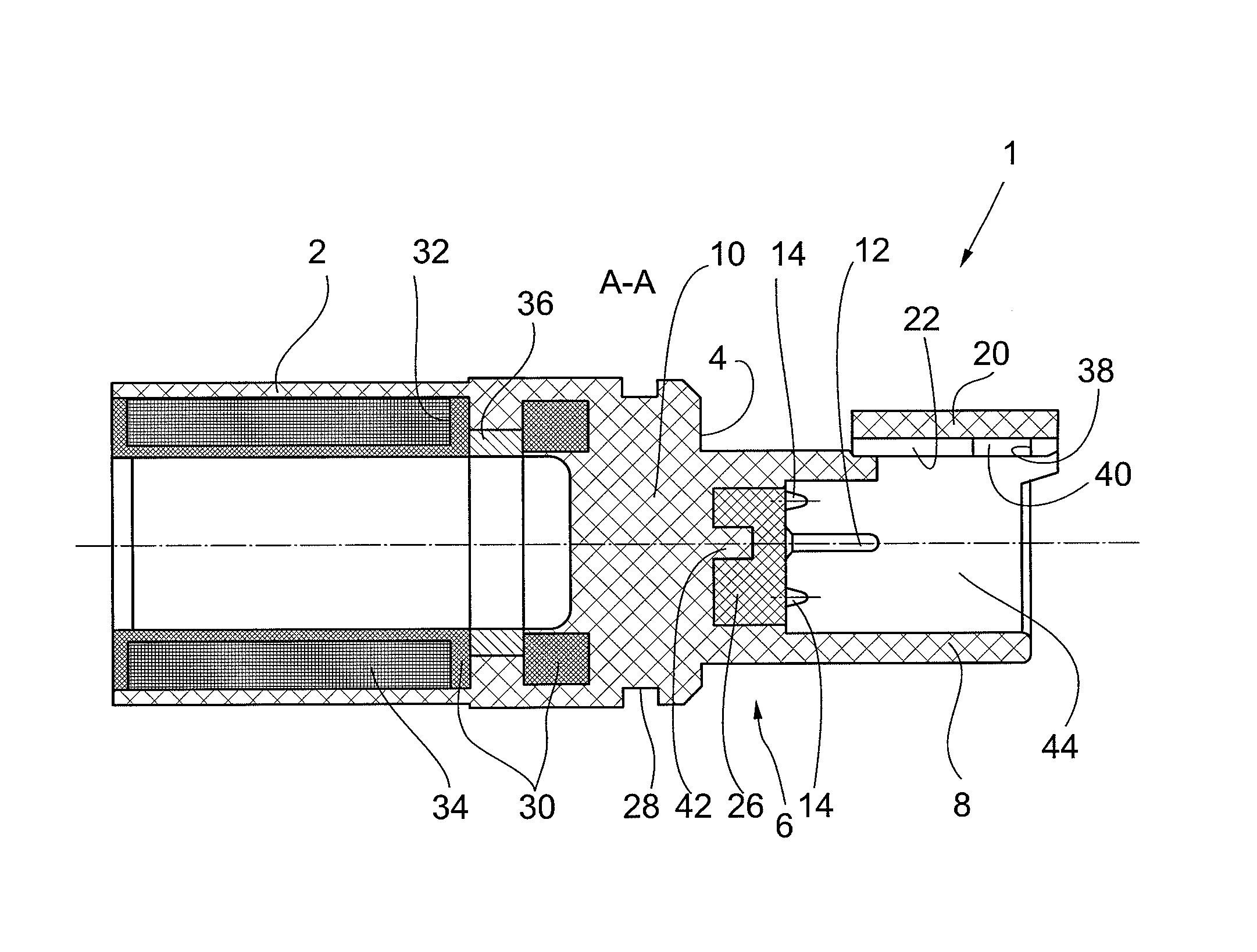
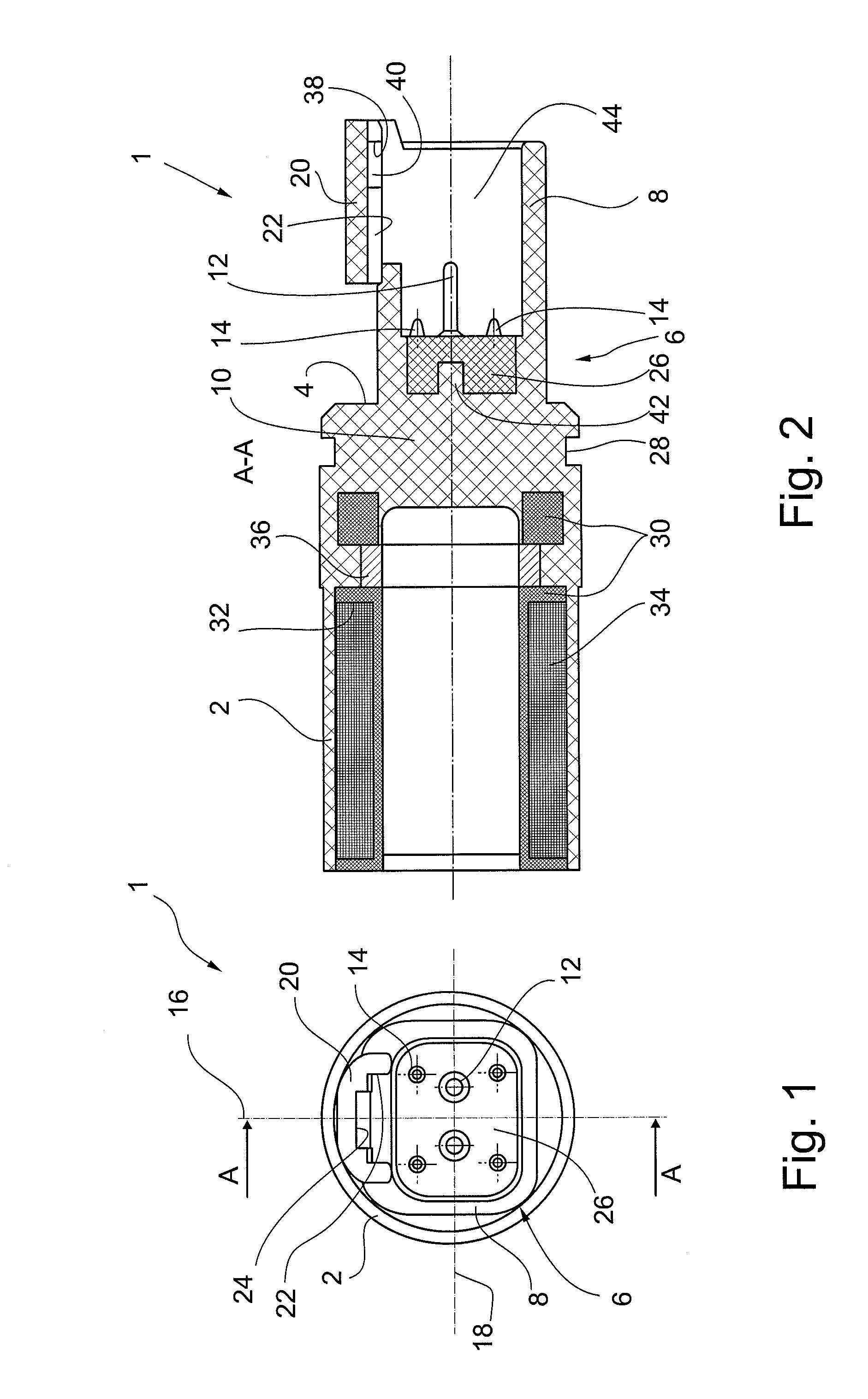
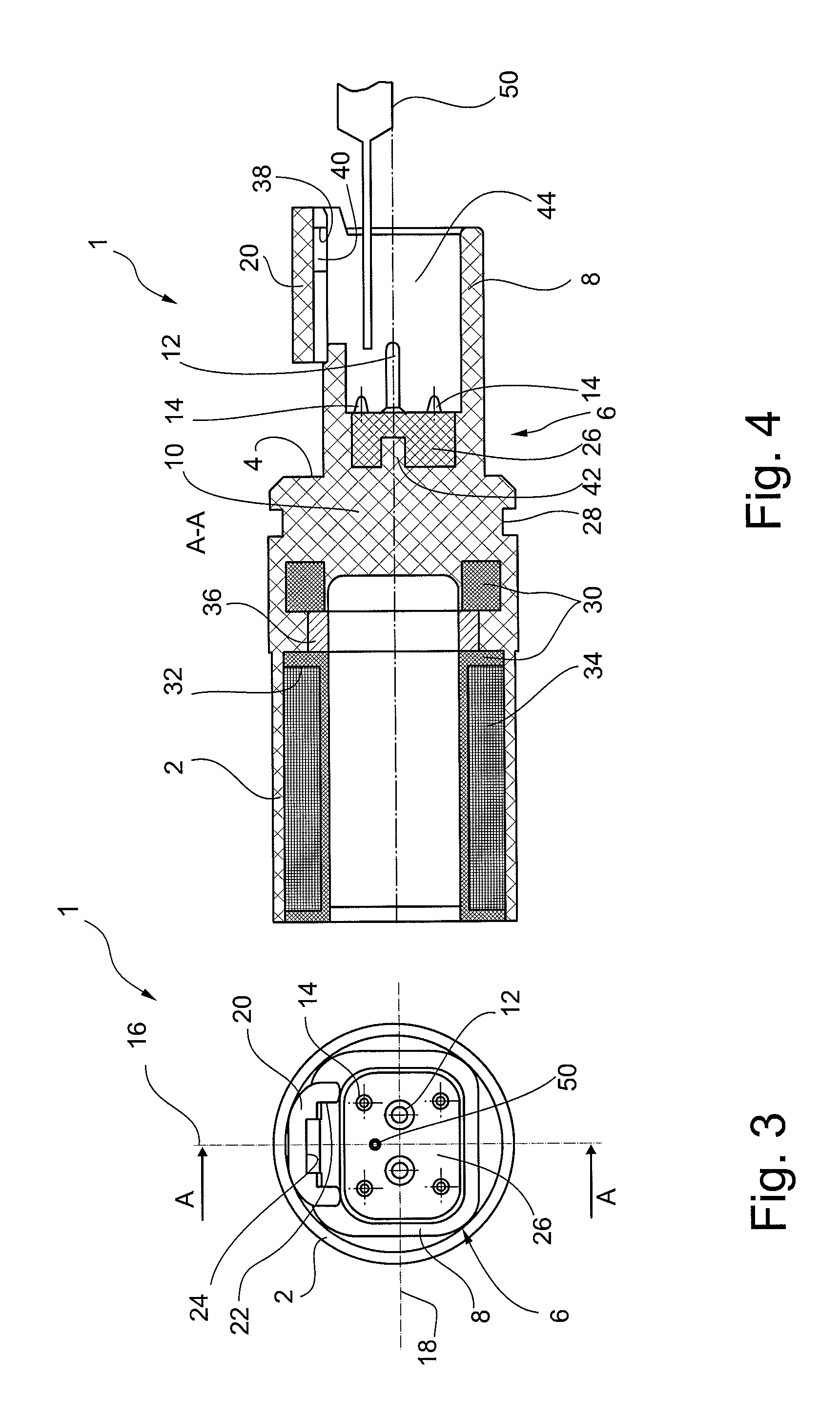
[0034]FIG. 1 shows a connector 1 for power supply of a coil of a solenoid (not shown) by which a pilot valve of the mobile hydraulics is controllable in a front view. The connector 1 is made of plastic material as an injection molded part. It has a substantially circular-cylindrical connector casing 2 provided for the arrangement in a corresponding breakout of a casing of the solenoid (not shown). The connector casing 2 has an end face 4 from which a connector device 6 extends toward the viewer of FIG. 1. The connector device 6 has an approximately rectangular connector collar 8 with rounded corners. Thereby the connector collar 8 borders a connector bottom 10 of the connector 1. In the area of the connector bottom 10 two current paths 12 in the form of pins and four smaller spacers 14 are disposed symmetrically with respect to a vertical axis 16 of the connector 1. Above a cross axis 18 extending through centers of the two current paths 12 an engaging carrier 20 is disposed at the ...


PUM


Abstract

A connector for electrical supply of a unit of the hydraulics which can be arranged or is arranged at a casing of such unit. Thereby at least one current path penetrates a connector bottom of the connector and the connector bottom is sealed with a silicone-containing compound against penetrating moisture in an area of this passage. The compound is an adhesive having high adhesive forces. A casing of a unit of the hydraulics can include such connector. A method of sealing a connector bottom of a connector penetrated by a current path is disclosed via which connector a unit of the hydraulics is adapted to be electrically supplied, the method includes a step of sealing a passage of the current path through the connector bottom with silicone-containing adhesive.

Description

BACKGROUND[0001]The invention relates to a sealed connector in accordance with the preamble of claim 1 and a method of sealing a connector in accordance with the preamble of claim 13.[0002]Control elements of the hydraulics, for example valves, can be actuated electromagnetically. For this purpose the valve includes an encapsulated solenoid having a coil via the current feed of which an armature is moved that entrains a valve piston. In this way a position of the valve piston can be precisely adjusted. For the current supply of the coil a connector penetrating the casing which is preferably made of plastic material and is injection-molded to the casing is provided at the casing of the solenoid. Current paths or pins of the connector connectable to a power source pass through a connector bottom of the connector from an outside toward an inside of the casing where they are connected to the coil.[0003]It is known to pot the connector bottom of the connector with a dielectric sealing co...

Claims


Application Information

Patent Timeline
Patent Type & Authority Patents(United States)
IPC IPC(8): H01R13/52H01R43/00H01R13/405
CPCH01R13/52H01R13/405H01R13/5216H01R43/005
Inventor ZAISER, LIEBHARTWENZLER, THOMAS
Owner ROBERT BOSCH GMBH
Why Eureka
Try Eureka