Torque limiter, wind turbine and wind turbine generator

a torque limiter and wind turbine technology, applied in the direction of machines/engines, couplings, slip couplings, etc., can solve the problems of damage to the motor, the torque limiter is not able to interrupt the transmission of torque, and the damage to the motor still occurs

Active Publication Date: 2016-09-13
JTEKT CORP
View PDF31 Cites 1 Cited by
  • Summary
  • Abstract
  • Description
  • Claims
  • Application Information

AI Technical Summary

Benefits of technology

[0008]One object of the invention is to provide a torque limiter, a wind turbine and a wind turbine generator that are configured such that transmission of excessively high torque is interrupted regardless of whether the excessively high torque is applied in the forward rotation direction or in the reverse rotation direction.

Problems solved by technology

Such a wind turbine generator has a problem that, when an abrupt change occurs in the wind speed or in the wind direction, excessively high torque acts on the motors and the speed reducers of the pitch drive devices and the yaw drive devices, which may cause damages to the motors and the speed reducers.
However, when the inner ring and the outer ring are rotating relative to each other in the other direction (the direction opposite to the one direction), the torque limiter is not able to interrupt the transmission of torque.
Therefore, in the case where the motor is rotated in the forward rotation direction and the reverse rotation direction as in each of the aforementioned pitch drive devices and yaw drive devices, the problem that damages are given to the motor still occurs if excessively high torque is applied in the other direction.

Method used


Image

  • Torque limiter, wind turbine and wind turbine generator
  • Torque limiter, wind turbine and wind turbine generator
  • Torque limiter, wind turbine and wind turbine generator

Examples


Embodiment Construction

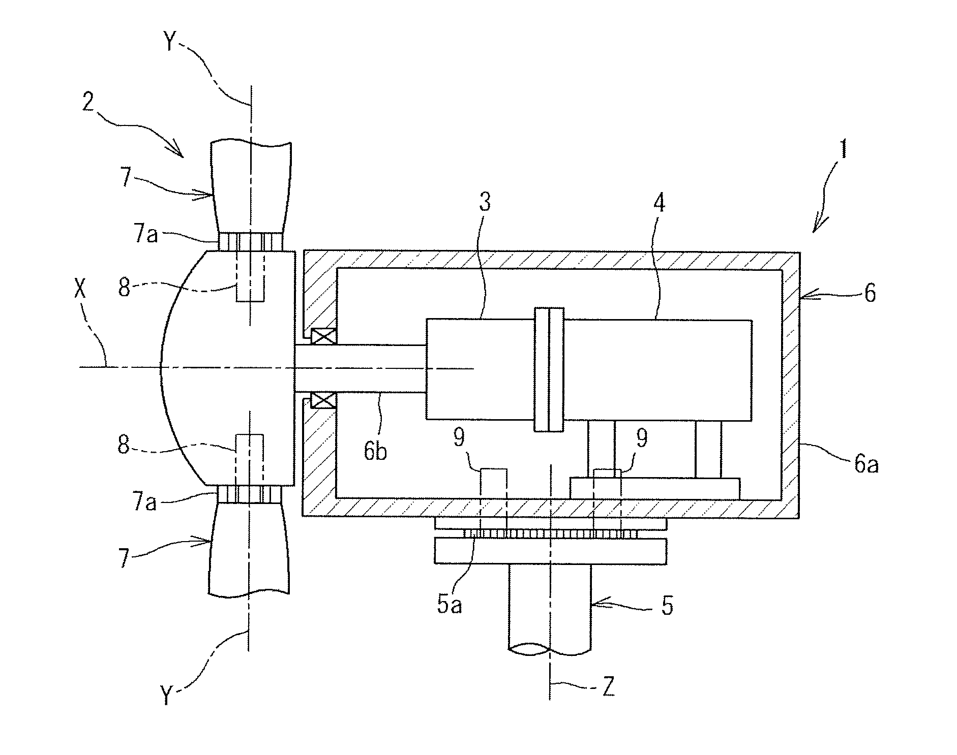
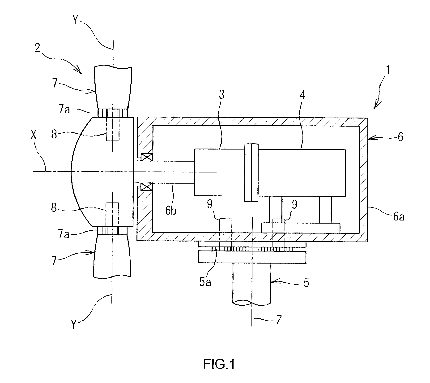
[0016]Hereinafter, embodiments of the invention will be described in detail with reference to the accompanying drawings. FIG. 1 is a sectional view illustrating a wind turbine generator 1 according to an embodiment of the invention. As illustrated in FIG. 1, the wind turbine generator 1 includes a wind turbine 2, a speed increaser 3 and a generator 4. The wind turbine 2 has a plurality of blades 7 that revolve upon reception of force of wind. The speed increaser 3 increases the speed of rotation produced by the blade 7. The generator 4 is connected to the speed increaser 3. The generator 4 is configured such that when the rotation of which the speed has been increased by the speed increaser 3 is input into the generator 4, a rotor (not shown) is driven and electricity is generated as the rotor is driven.

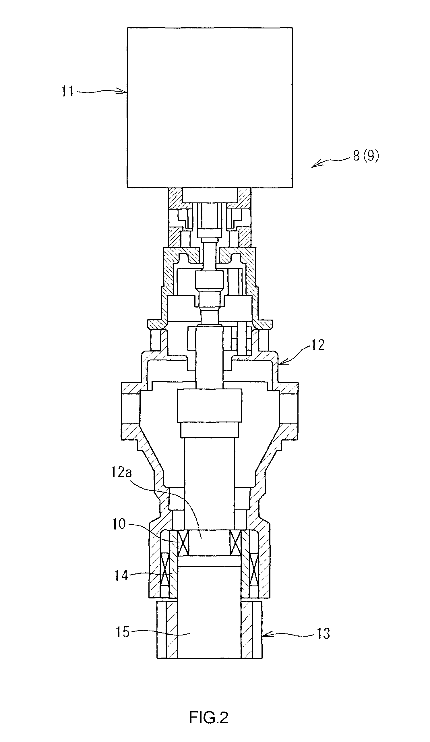
[0017]The wind turbine 2 includes a tower 5, a nacelle 6, the blades 7, pitch drive devices 8, yaw drive devices 9 and torque limiters 10 (see FIG. 2). The nacelle 6 is formed of a c...


PUM


Abstract

In a torque limiter, wedge-shaped spaces are formed between inner and outer rings so as to be arranged in the circumferential direction. In each wedge-shaped space, there are arranged a first roller and a second roller that transmit torque between the inner and outer rings by being brought into wedge-engagement when the inner and outer rings rotate relative to each other in one direction and in the other direction, respectively. Between the first and second rollers, there is arranged an urging device that urges the first and second rollers in such directions that the first and second rollers are brought into wedge-engagement. Each wedge-shaped space is formed such that when the torque becomes equal to or higher than a predetermined value, a first wedge angle of the first roller or a second wedge angle of the second roller becomes such an angle that wedge-engagement of the roller is cancelled.

Description

INCORPORATION BY REFERENCE[0001]The disclosure of Japanese Patent Application No. 2012-209649 filed on Sep. 24, 2012 including the specification, drawings and abstract, is incorporated herein by reference in its entirety.BACKGROUND OF THE INVENTION[0002]1. Field of the Invention[0003]The invention relates to a torque limiter, a wind turbine, and a wind turbine generator.[0004]2. Description of the Related Art[0005]A wind turbine generator includes pitch drive devices used to adjust the pitch angle of blades of a wind turbine and yaw drive devices used to turn a blade-supporting nacelle relative to a tower. Each of the pitch drive devices and the yaw drive devices is formed of a combination of a motor capable of rotating in the forward rotation direction and the reverse rotation direction and a speed reducer (see, for example, Japanese Patent Application Publication No. 2010-1996 (JP 2010-1996 A)). Such a wind turbine generator has a problem that, when an abrupt change occurs in the ...

Claims


Application Information

Patent Timeline
Patent Type & Authority Patents(United States)
IPC IPC(8): F16D7/02F16D43/20F03D7/02F16D7/00F16D41/066F16D41/10
CPCF03D7/02F16D7/00F16D41/066F16D41/105F16D43/20F16D2041/0665Y02E10/722Y02E10/723Y02E10/72
Inventor FUJIWARA, HIDEKI
Owner JTEKT CORP
Why Eureka
Try Eureka