Ion source for mass spectrometry

a mass spectrometry and ion source technology, applied in the direction of instruments, particle separator tubes, components, etc., can solve the problems of adverse thermal effects on the ion source probe, adverse effects on the performance of the mass spectrometer, and instability in the generation of the sample plume, so as to improve the desolvation of the sample stream, improve the sampling efficiency, and increase the flow rate

Active Publication Date: 2018-01-16
DH TECH DEVMENT PTE
View PDF7 Cites 8 Cited by
  • Summary
  • Abstract
  • Description
  • Claims
  • Application Information

AI Technical Summary

Benefits of technology

[0006]Though the use of elevated temperatures within the ionization chamber may be necessary to improve desolvation of the sample stream, and thus improve sampling efficiency, conventional desolvation techniques can cause adverse thermal effects on the ion source probe (e.g., a stainless steel capillary tube), which extends into the heated ionization chamber. As the ion source probe heats up, the flow of sample liquid within the probe can be vaporized, thereby causing instability in the generation of the sample plume. By way of example, as the vaporizing liquid rapidly expands within the probe, some sample liquid downstream of this vapor “plug” may be ejected more forcefully from the probe, thereby increasing the flow rate of liquid sample ejected from the probe, the size of the plume discharged by the probe, and / or the velocity of the fluid droplets within the plume. Moreover, as the vapor plug itself is discharged from the probe into the ionization chamber, the transmission of ions into the mass spectrometer can be interrupted as the probe is temporarily dry.

Problems solved by technology

Conventional desolvation techniques utilizing elevated temperatures, however, can pose challenges that adversely affect the performance of the mass spectrometer, especially during extended sampling runs and / or in combination with low flow rate sample sources (e.g., liquid chromatography (LC) based separation processes).
Though the use of elevated temperatures within the ionization chamber may be necessary to improve desolvation of the sample stream, and thus improve sampling efficiency, conventional desolvation techniques can cause adverse thermal effects on the ion source probe (e.g., a stainless steel capillary tube), which extends into the heated ionization chamber.
As the ion source probe heats up, the flow of sample liquid within the probe can be vaporized, thereby causing instability in the generation of the sample plume.

Method used


Image

  • Ion source for mass spectrometry
  • Ion source for mass spectrometry
  • Ion source for mass spectrometry

Examples


examples

[0047]The applicants' teachings can be more fully understood with reference to the examples and resulting data that follow. Other embodiments of the applicants' teachings will be apparent to those skilled in the art from consideration of the present specification and practice of the present teachings disclosed herein. It is intended that these examples be considered as exemplary only. The examples are provided for illustrative purposes and do not necessarily indicate optimal ways of implementing applicants' teachings or optimal results that can be obtained.

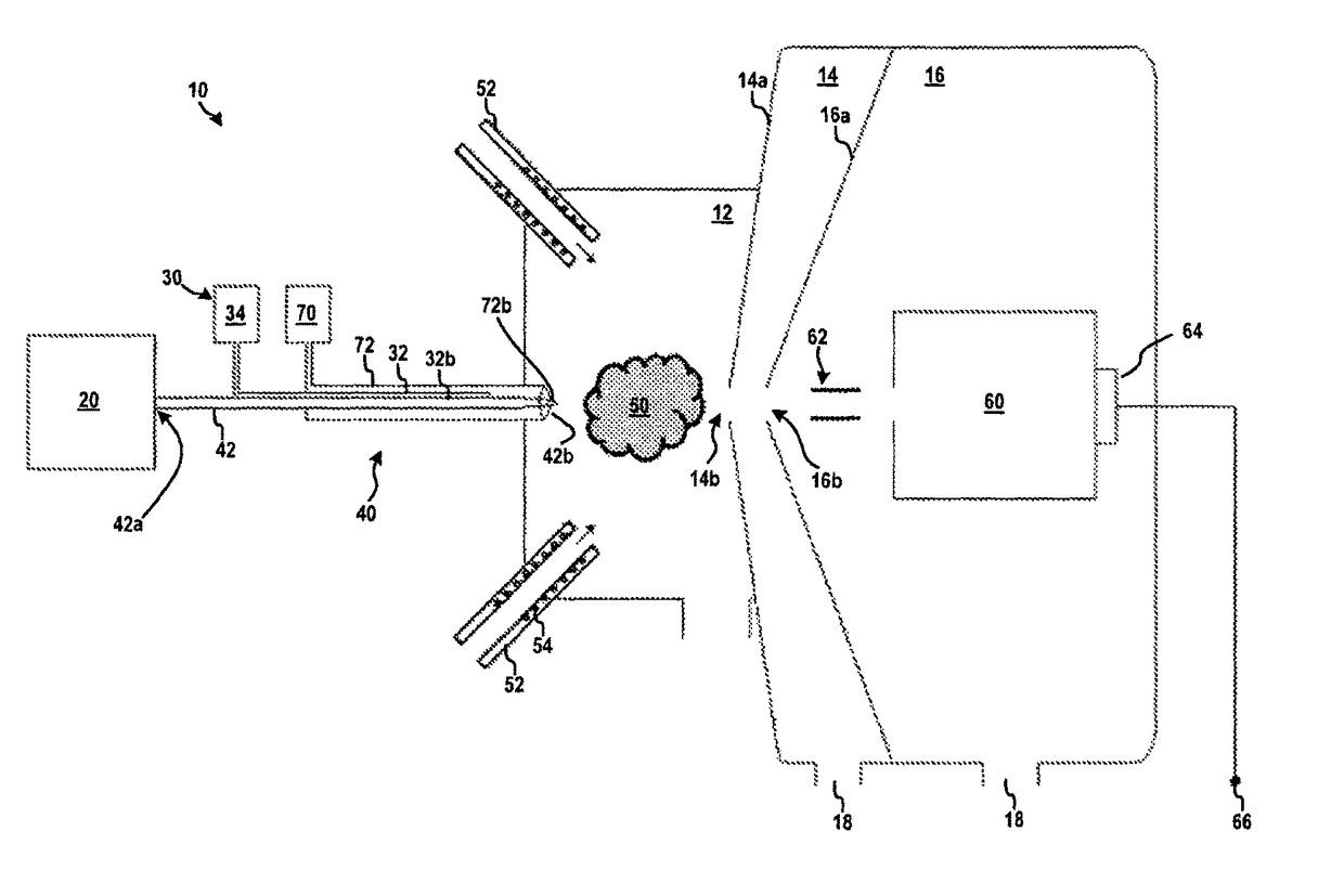
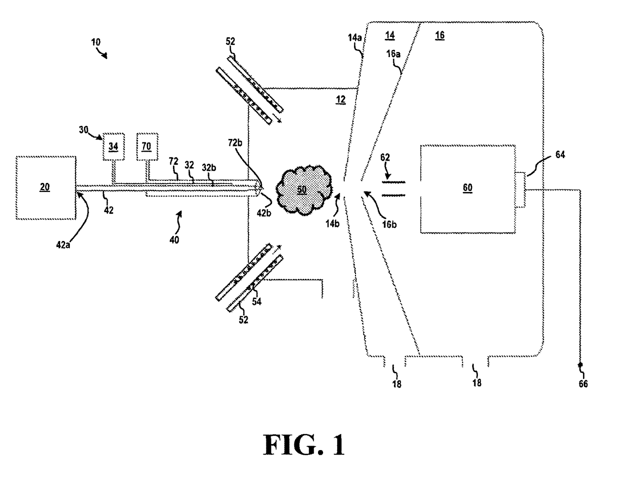
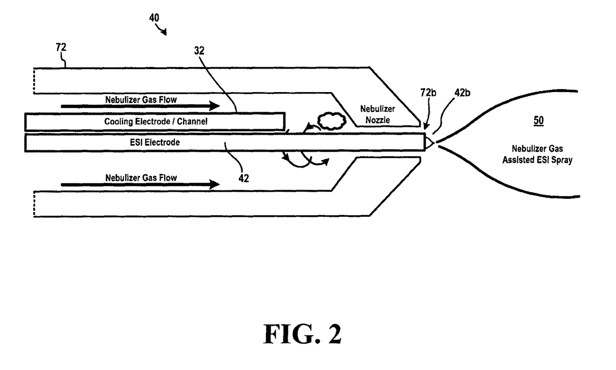
[0048]The cooling of the ion source in systems and methods according to the teachings herein can result in improved stability of the ion signal relative to that produced by un-cooled prior art ion sources. For example, a prototype system employing a cooling conduit 32 for discharging a cooling fluid within the channel of the nebulizer shaft 72 as described in FIGS. 1 and 2 was produced to generate the exemplary histogram depicted ...


PUM

PropertyMeasurementUnit
temperatureaaaaaaaaaa
fluid flow rateaaaaaaaaaa
temperatureaaaaaaaaaa

Abstract

Systems and methods for delivering a sample to a mass spectrometer are provided. In one aspect, the systems and methods can provide efficient cooling of an ion source probe to prevent overheating and the resulting degradation in ion sampling. In some aspects, such cooling can result in improved consistency and/or efficiency of ion formation. Moreover, ion source cooling in accordance with various aspects of the present teachings can allow for the use of higher temperatures in the ionization chamber (thereby improving desolvation) and/or can enable the use of lower flow rate sample sources than with conventional techniques.

Description

RELATED APPLICATION[0001]This application claims priority to U.S. provisional application No. 61 / 919,125, filed on Dec. 20, 2013, which is incorporated herein by reference in its entirety.FIELD[0002]The present teachings relate to methods, systems and apparatus for generating ions from a sample (e.g., containing an analyte of interest) for mass spectrometric analysis.INTRODUCTION[0003]Mass spectrometers allow detection, identification, and quantification of chemical entities in samples. Mass spectrometers detect the chemical entities as ions such that a conversion of the chemical entities to charged ions must occur during the sampling process. Liquid samples are conventionally converted into gas phase by employing atomizers, nebulizers, and / or electro sprayers, which can produce a plume of liquid sample droplets (e.g., a plurality of micro droplets entrained in a carrier gas directed toward a sampling orifice of a mass spectrometer). Often a desolvation step is utilized in the sampl...

Claims


Application Information

Patent Timeline
Patent Type & Authority Patents(United States)
IPC IPC(8): H01J49/00H01J49/04H01J49/16G01N30/72
CPCH01J49/045G01N30/724H01J49/044H01J49/167H01J49/0404G01N30/7273G01N30/7246H01J49/0468
Inventor COVEY, THOMAS RKOVARIK, PETER
Owner DH TECH DEVMENT PTE
Why Eureka
Try Eureka