
Droplet manipulation using gas-phase standing-wave ultrasound fields in MS sources

a technology of standing wave ultrasound and droplet, which is applied in the field of droplet manipulation using gas-phase standing wave ultrasound fields in ms sources, can solve the problems of droplet emission and loss of analyte signal, and achieve the effect of reducing the average size of droplets

Active Publication Date: 2015-05-26
MICROMASS UK LTD
View PDF9 Cites 2 Cited by
  • Summary
  • Abstract
  • Description
  • Claims
  • Application Information

AI Technical Summary

Benefits of technology

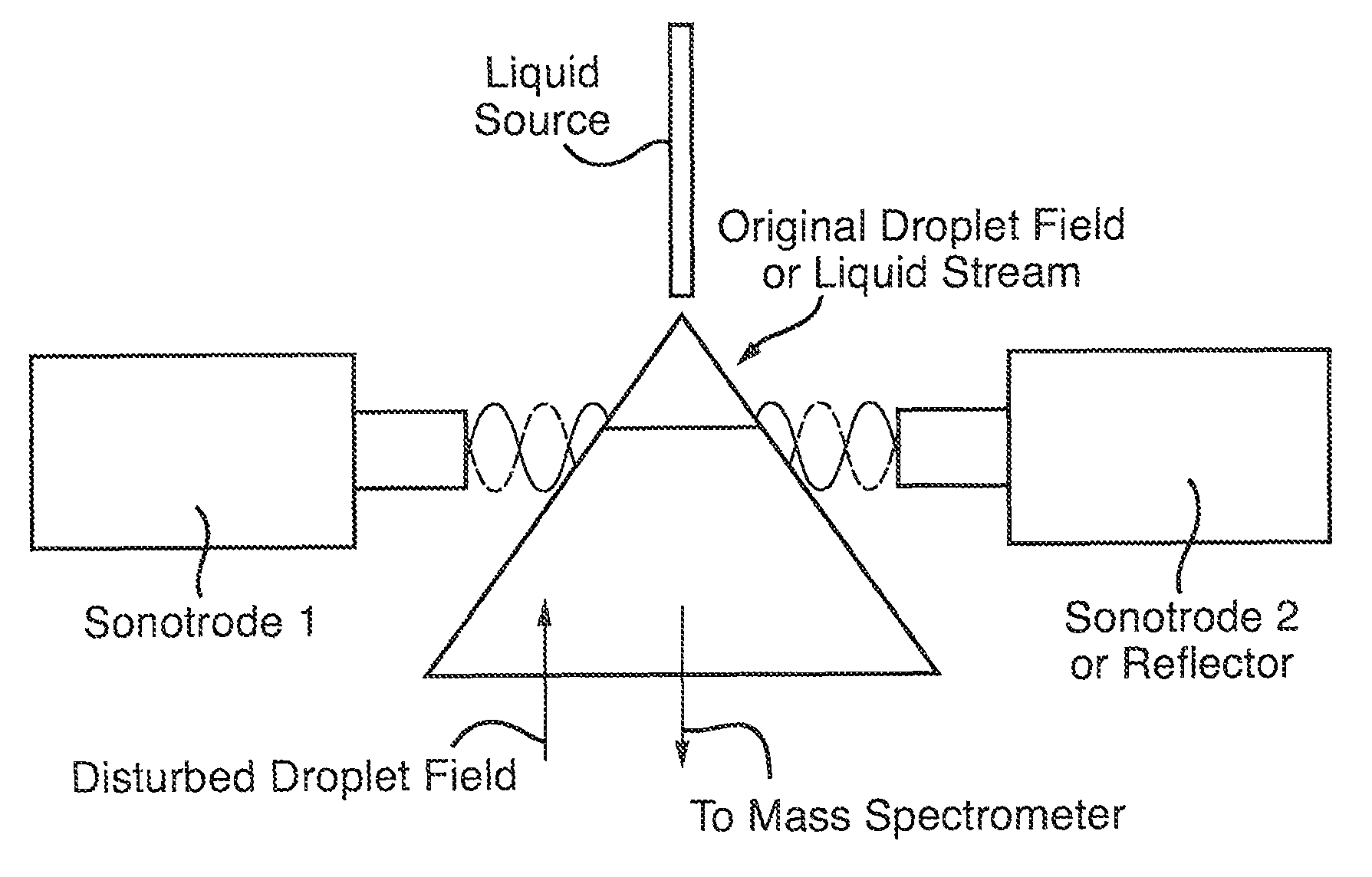
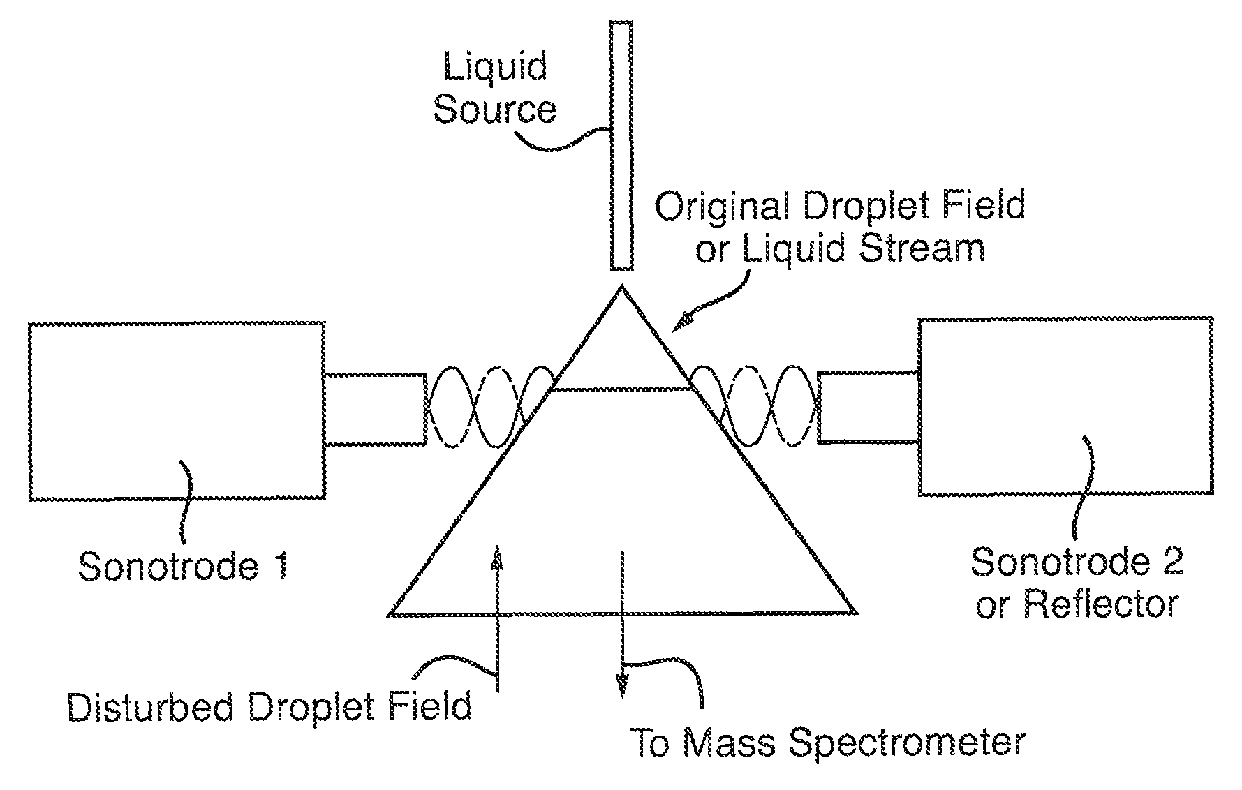
[0009]One of the problems with certain types of conventional ion sources such as Electrospray ion sources is that they can emit droplets at least some of which have a relatively large diameter. The relatively large droplets do not then completely desolvate which results in a loss of analyte signal. The solution to this problem according to the present invention is to provide one or more ultrasonic transmitters downstream of the ionisation device (e.g. Electrospray ion source). The one or more ultrasonic transmitters create acoustic standing waves which, for example, further nebulise the stream of droplets emitted from the ionisation device. As a result, the droplets are significantly reduced in size by the acoustic standing waves resulting in significantly improved desolvation compared to conventional arrangements. Furthermore, the nodes of the acoustic standing waves can be adjusted in order to optimise the subsequent transmission of analyte sample into and through the sampling orifice of the mass spectrometer thereby improving sensitivity.
[0019]The one or more acoustic standing waves are preferably arranged so as to result in a reduction of the average size of droplets in the stream of droplets.

Problems solved by technology

One of the problems with certain types of conventional ion sources such as Electrospray ion sources is that they can emit droplets at least some of which have a relatively large diameter.
The relatively large droplets do not then completely desolvate which results in a loss of analyte signal.

Method used


Image

  • Droplet manipulation using gas-phase standing-wave ultrasound fields in MS sources
  • Droplet manipulation using gas-phase standing-wave ultrasound fields in MS sources

Examples


Embodiment Construction

[0059]A preferred embodiment of the present invention will now be described.

[0060]FIG. 1 shows a preferred embodiment of the present invention wherein a stream of droplets is emitted from a liquid source such as an Electrospray ion source and interacts with an acoustic standing wave generated by two sonotrodes or one sonotrode and a reflector.

[0061]According to an embodiment one or more standing-wave acoustic fields are introduced into a mass spectrometer (MS) source which has several benefits when an analyte is introduced in a stream of liquid or liquid droplets by e.g. Electrospray.

[0062]One of the limitations of known liquid interface MS sources is a loss of analyte due to incomplete desolvation of large droplets. Advantageously, according to the preferred embodiment large droplets can be broken up by acoustic fields. The resulting droplets can be sampled more efficiently into a first vacuum stage of a mass spectrometer and they will also evaporate faster thereby improving the se...


PUM

PropertyMeasurementUnit
frequencyaaaaaaaaaa
frequencyaaaaaaaaaa
massaaaaaaaaaa

Abstract

An ion source for a mass spectrometer is disclosed comprising an ionization device which emits a stream of droplets and one or more ultrasonic transmitters which create one or more acoustic standing waves. The acoustic standing waves may be used to further nebulize the stream of droplets and induce internal mixing of the droplets.

Description

CROSS-REFERENCE TO RELATED APPLICATION[0001]This application is the National Stage of International Application No. PCT / GB2012 / 052900, filed 22 Nov. 2012, which claims priority from and the benefit of United Kingdom Patent Application No. 1120143.1 filed on 22 Nov. 2011. The entire content of this application is incorporated herein by reference.BACKGROUND OF THE PRESENT INVENTION[0002]It is known that gas-phase acoustic fields induce local pressure differences around the surfaces of liquid droplets (King, L. V. Proc. Roy. Soc., A147, 212-240 (1934)). The forces produced by acoustic standing waves are significantly larger than those produced by travelling waves. Acoustic standing waves can be produced either using an ultrasound transmitter (sonotrode) and a reflector or by using a pair of ultrasound transmitters.[0003]It is known to cause droplets to be levitated in the nodes of standing-wave ultrasound fields. Similar techniques are used for lateral stabilization of droplet position...

Claims


Application Information

Patent Timeline
Patent Type & Authority Patents(United States)
IPC IPC(8): H01J49/10H01J49/16H01J49/26G01N27/62G01N29/22H01J49/24
CPCH01J49/165H01J49/26G01N27/622G01N29/22H01J49/24H01J49/0454Y10T137/0391Y10T137/206G01N27/623H01J49/0431H01J49/10H01J49/0031H01J49/022
Inventor MORRIS, MICHAEL RAYMONDPRINGLE, STEVEN DEREKRICHARDSON, KEITH
Owner MICROMASS UK LTD
Learn More