
Ion transfer arrangement

A technology of ion migration and ion migration, which is applied in the field of high vacuum ion migration devices, and can solve the problems of high loss due to space charge effects

Inactive Publication Date: 2012-06-20
THERMO FISHER SCI BREMEN
View PDF15 Cites 0 Cited by
  • Summary
  • Abstract
  • Description
  • Claims
  • Application Information

AI Technical Summary

Problems solved by technology

However, the gas velocity is much lower in this region than on the inside of the tube, and thus space charge effects generate higher losses

Method used


Image

  • Ion transfer arrangement
  • Ion transfer arrangement
  • Ion transfer arrangement

Examples


Embodiment Construction

[0035] Detailed description of the preferred embodiment

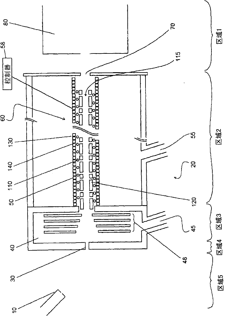
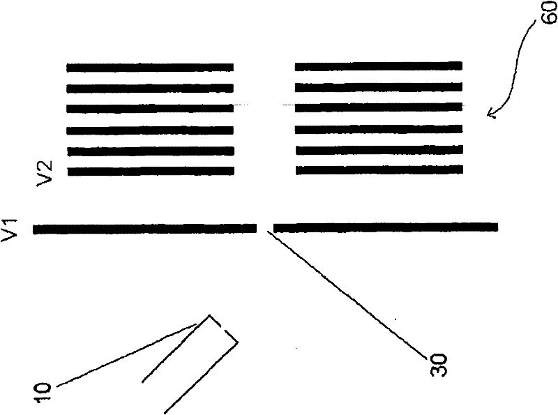
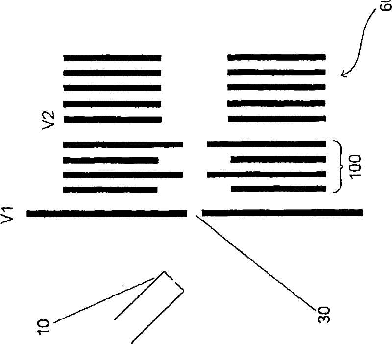
[0036] figure 1 An ion transport device employing aspects of the invention is shown for transporting ions between an atmospheric pressure ion source (eg, electrostatic spray) and the high vacuum of a subsequent vacuum chamber in which one or more stages of mass spectrometry measurements are located. exist figure 1 Here, an ion source 10 such as, but not limited to, an electrostatic spray source, an atmospheric pressure chemical ionization (APCI) or an atmospheric pressure photoionization (APPI) source is located at atmospheric pressure. This generates ions in a known manner and the ions enter the ion transport device (indicated generally at 20) via the entrance aperture 30. The ions then pass through the first pump transport chamber 40 (hereinafter referred to as the expansion chamber 40 ) and continue into the second vacuum chamber 50 containing the ion conduit 60 . The ions exit conduit 60 and pass through the exit...


PUM


Abstract

A method of transferring gas and ions between a relatively higher pressure region and a relatively lower pressure region of a mass spectrometer comprises: providing an ion conduit (60) between the relatively higher pressure region and the relatively lower pressure region. The ion conduit (60) includes an electrode assembly (300) defining an ion transfer channel. The electrode assembly (300) has a first group of ring electrodes (305) with a first width D1, and a second group of ring electrodes alternately with the first ring electrodes (305) with a second width D2 (>=D1). A DC voltage with a V1 voltage and a first polarity is supplied to the first ring electrodes (205) and a DC voltage with a V2 (may be less than or equal to V1) voltage and an opposite polarity is applied to the second ring electrodes (310). The pressure of the ion conduit (60) is controlled to facilitate to maintain the viscous flow of the gas and ion in the ion transfer channel.

Description

field of invention [0001] The present invention relates to ion transport devices for transporting ions within a mass spectrometer, and more particularly to high vacuum ion transport devices for transporting ions from an atmospheric pressure ionization source to a vacuum chamber of a mass spectrometer. Background of the invention [0002] Ion transfer tubes, also known as capillaries, are well known in the art of mass spectrometry for transporting ions between an ionization chamber maintained at or near atmospheric pressure and a second chamber maintained at reduced pressure. In general, ion transport channels usually take the form of elongated narrow tubes (capillaries) having an inlet end open to the ionization chamber and an outlet end open to the second chamber. Ions enter the ion transfer capillary along with charged and uncharged particles (e.g., partially desolvated droplets from electrostatic spray or APCI probes, or ions and neutrons and matrix / matrix from laser deso...

Claims


Application Information

Patent Timeline
Patent Type & Authority Patents(China)
IPC IPC(8): H01J49/06
Inventor A·马卡洛夫R·佩施R·马雷克V·科兹洛夫斯基
Owner THERMO FISHER SCI BREMEN
Learn More