Electromagnetic induction sensor, overlay member for electromagnetic induction sensor, and manufacturing method of electromagnetic induction sensor

a manufacturing method and technology of electromagnetic induction sensor, applied in the direction of electrical/magnetically converting sensor output, liquid/fluent solid measurement, instruments, etc., can solve the problems of large characteristic variation, difficult cutting of amorphous alloy, etc., to achieve easy stamping, easy cutting, and low hardness

Active Publication Date: 2016-09-13
WACOM CO LTD
View PDF13 Cites 4 Cited by
  • Summary
  • Abstract
  • Description
  • Claims
  • Application Information

AI Technical Summary

Benefits of technology

[0022]In view of the above points, an aspect of the invention is directed to overcoming the difficulty in manufacturing an electromagnetic induction sensor and enabling enhancement in the detection accuracy of the coordinates of a position indicated by a position indicator on the electromagnetic induction sensor.
[0026]The reason why such configuration is possible is because the magnetic powder material layer composed of the magnetic powder material is used as the magnetic path material. Specifically, the magnetic powder material layer has lower hardness compared with the amorphous alloy layer of the related art and is easy to cut. Therefore, according to the embodiment of the invention, after the overlay member having at least the magnetic powder material layer is deposited on (adhered to) the sensor board main body, the entire (integral) assembly can be easily stamp-cut into a desired shape with a cutter. Thus, the manufacturing becomes easy and the mass productivity is enhanced.
[0027]Furthermore, it is easy to form the magnetic powder material layer using the magnetic powder material while minimizing variation in the characteristics thereof. Therefore, according to the electromagnetic induction sensor of the embodiment of the invention, the detection accuracy of the coordinates of a position indicated by the position indicator can be improved.
[0028]Moreover, the magnetic powder material can be made not as a good conductor with low resistance like an amorphous alloy in the related art, but as a poor conductor specifically formulated to have high resistance by mixing in a resin. Thus, it is also possible to omit an insulator layer between the second surface side of the sensor board main body and the magnetic powder material layer and instead to directly deposit (adhere) the magnetic powder material layer on (to) the second surface side of the sensor board main body. In this case, because the insulator layer between the second surface side of the sensor board main body and the magnetic powder material layer is unnecessary, correspondingly the thickness can be reduced.
[0029]According to the embodiment of the invention, it is possible to provide an electromagnetic induction sensor that overcomes manufacturing difficulty and enables enhancement in the detection accuracy of the coordinates of a position indicated by a position indicator.
[0030]Furthermore, the electromagnetic induction sensor according to exemplary embodiments of the invention is integrally formed, wherein the sensor board main body integrally includes the magnetic path material. Thus, the adhesive layer (24 in FIG. 10B) used in the case of separately configuring the sensor board and the magnetic path material and joining them can be omitted in these embodiments, in addition to that the unnecessary overlay (15 in FIG. 10A) can be omitted. Therefore, the thickness of the electromagnetic induction sensor can be reduced.

Problems solved by technology

The amorphous alloy is very hard and is not easy to cut.
Furthermore, the amorphous alloy, which has a non-crystalline structure, has large characteristic variation due to difficulty in manufacturing.

Method used


Image

  • Electromagnetic induction sensor, overlay member for electromagnetic induction sensor, and manufacturing method of electromagnetic induction sensor
  • Electromagnetic induction sensor, overlay member for electromagnetic induction sensor, and manufacturing method of electromagnetic induction sensor
  • Electromagnetic induction sensor, overlay member for electromagnetic induction sensor, and manufacturing method of electromagnetic induction sensor

Examples


first embodiment

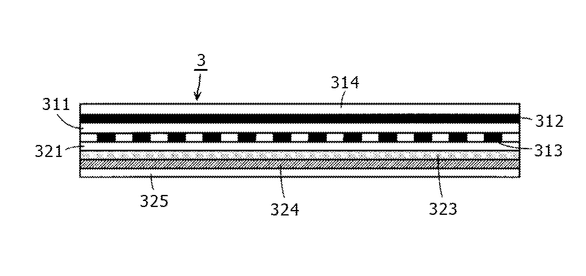
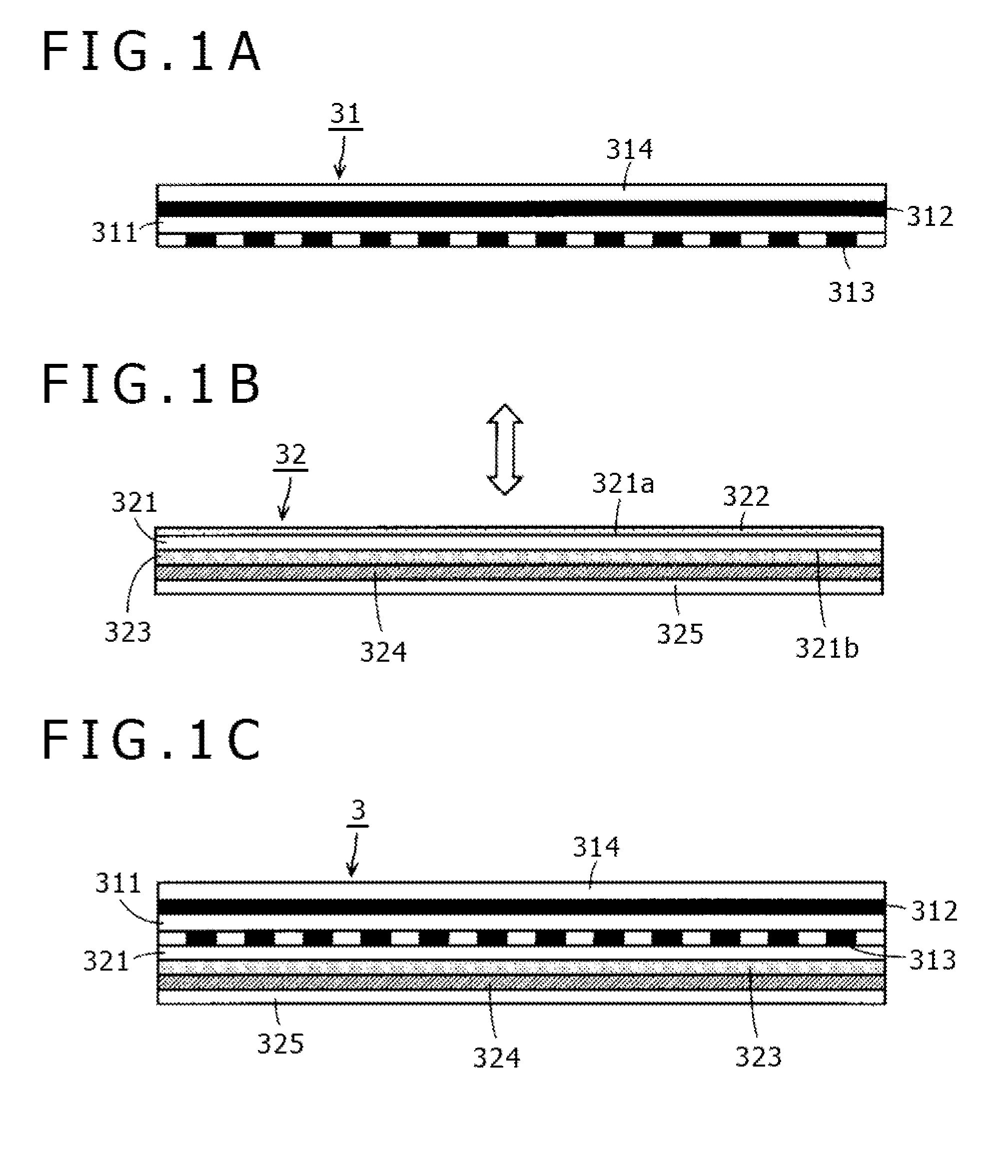
[0043]FIGS. 1A to 1C are sectional views showing a configuration example of an electromagnetic induction sensor according to a first embodiment of the invention. An electromagnetic induction sensor 3 of the first embodiment is composed of a sensor board main body 31 shown in FIG. 1A and an overlay member 32 shown in FIG. 1B. The sensor 3 is integrally formed by depositing (adhering) the overlay member 32 on (to) the sensor board main body 31 (see FIG. 1C).

[0044]As shown in FIG. 1A, in the sensor board main body 31, an X-axis-direction loop coil group conductor 312 is disposed on one surface side of an insulating substrate 311 composed of, for example, PET and a Y-axis-direction loop coil group conductor 313 is disposed on the other surface side opposite from the one surface. Furthermore, in the example of FIG. 1A, a surface sheet (overlay) 314 formed of, for example, a PET film is so deposited (adhered) as to cover the X-axis-direction loop coil group conductor 312 as a whole. A pos...

second embodiment

[0103]In the above-described first embodiment, with respect to the Y-axis-direction loop coil group conductor 313 of the sensor board main body 31, the magnetic powder material layer 323 is deposited (adhered / applied) with the intermediary of an insulating layer formed of the overlay base film 321. However, because the magnetic powder material layer 323 has resistance as high as 100 kΩ as shown in the table of FIG. 5, even when the insulating layer formed of the overlay base film 321 is not provided, there may be practically no influence on the electrical characteristics of the Y-axis-direction loop coil group conductor 313. Thus, the overlay base film 321 may be omitted. By employing the configuration in which the insulating layer formed of the overlay base film 321 is not provided, a sensor can be realized whose thickness is even smaller than that of the sensor 3 of the first embodiment.

[0104]The second embodiment provides an electromagnetic induction sensor having such configurat...

other embodiments and modification examples

[0125]In the explanation of the above-described embodiments, a material made into a coating material form or a material impregnated with an adhesive is used as the magnetic powder material. However, the magnetic powder material may be provided as a material obtained by mixing powder of a high-permeability amorphous metal or the like with a non-magnetic, non-conductive polymer material, such as resin, and solidifying the mixture. It should be apparent to those skilled in the art that the above-described stamping processing can be similarly performed in this case.

[0126]Although the number of processing steps is reduced in the above-described stamping processing, it should be apparent to those skilled in the art that the electromagnetic induction sensor of an embodiment of the present invention may be produced similarly to the related art. For example, a manufacturing method may be used, in which the overlay member 32 is subjected to outer shape processing (cut) in advance and the over...


PUM

PropertyMeasurementUnit
thicknessaaaaaaaaaa
thicknessaaaaaaaaaa
thicknessaaaaaaaaaa

Abstract

Disclosed herein is an electromagnetic induction sensor that is used with a position indicator and includes coils for electromagnetic coupling with the position indicator. The electromagnetic induction sensor includes: a sensor board main body that includes an insulating substrate and a surface sheet attached to a side of a first surface of the insulating substrate, on which side a position is indicated by the position indicator; at least part of conductors forming the coils being formed on a second surface of the insulating substrate opposite from the first surface; and an overlay member that includes a magnetic powder material layer and is adhered to the side of the second surface of the sensor board main body.

Description

CROSS REFERENCE TO RELATED APPLICATION[0001]The present application claims priority to Japanese Patent Application No. 2013-155204 filed on Jul. 26, 2013, the disclosure of which is hereby incorporated by reference in its entirety.BACKGROUND OF THE INVENTION[0002]1. Field of the Invention[0003]The invention relates to an electromagnetic induction sensor, an overlay member for an electromagnetic induction sensor, and a manufacturing method of an electromagnetic induction sensor.[0004]2. Description of the Related Art[0005]Position detecting devices of an electromagnetic induction system used with a pen-shaped position indicator have been widely used along with popularization of so-called tablet terminals, pad portable terminals, and portable information devices called personal digital assistants (PDA). Furthermore, as the thickness of these electronic apparatuses continues to be reduced, thickness of electromagnetic induction sensors used in the position detecting devices of the elec...

Claims


Application Information

Patent Timeline
Patent Type & Authority Patents(United States)
IPC IPC(8): G01B7/14G01D5/20G01F1/58H05K13/00
CPCG01D5/2073H05K13/00G01F1/582Y10T29/49155G06F3/046G01R33/0052
Inventor MATSUMOTO, YOSHIHARU
Owner WACOM CO LTD
Why Eureka
Try Eureka