Coil and solenoid valve

a solenoid valve and coil technology, applied in the direction of transformer/inductance casing, inductance, inductance, etc., can solve the problem of unsatisfactory gap formed between the yoke disk and the coil carrier, and achieve the effect of improving the conventional coil of the solenoid

Active Publication Date: 2016-09-13
SCHAEFFLER TECH AG & CO KG
View PDF14 Cites 0 Cited by
  • Summary
  • Abstract
  • Description
  • Claims
  • Application Information

AI Technical Summary

Benefits of technology

[0007]The present invention provides that the filler material that has to be injected into the intermediate space to seal the gap, hereinafter referred to as flow gap, should be compacted within the flow gap. If the compacting process takes too much time, the filler material exits again from the side of the flow gap situated opposite the intermediate space and must be removed from there by a complicated step, so that the duration of the production cycles of the coil is prolonged. The invention is therefore based on the idea of compacting the filler material already in the interior of the flow gap so that the flow gap is sealed by the filler material itself. In this way, it is assured that no filler material can exit on the side of the intermediate space on the side of flow gap situated opposite the intermediate space so that not only additional work steps for removing the filler material from the coil are avoided, but the filler material that has to be removed is also saved.
[0020]In a further embodiment, the filler material can be received in the intermediate space. The filler material protects the intermediate space from penetrating impurities and enhances the durability of the coil.

Problems solved by technology

Because of the tolerances, an undesired gap is formed between the yoke disk and the coil carrier and / or between the yoke disk and the pot.

Method used


Image

  • Coil and solenoid valve
  • Coil and solenoid valve
  • Coil and solenoid valve

Examples


Embodiment Construction

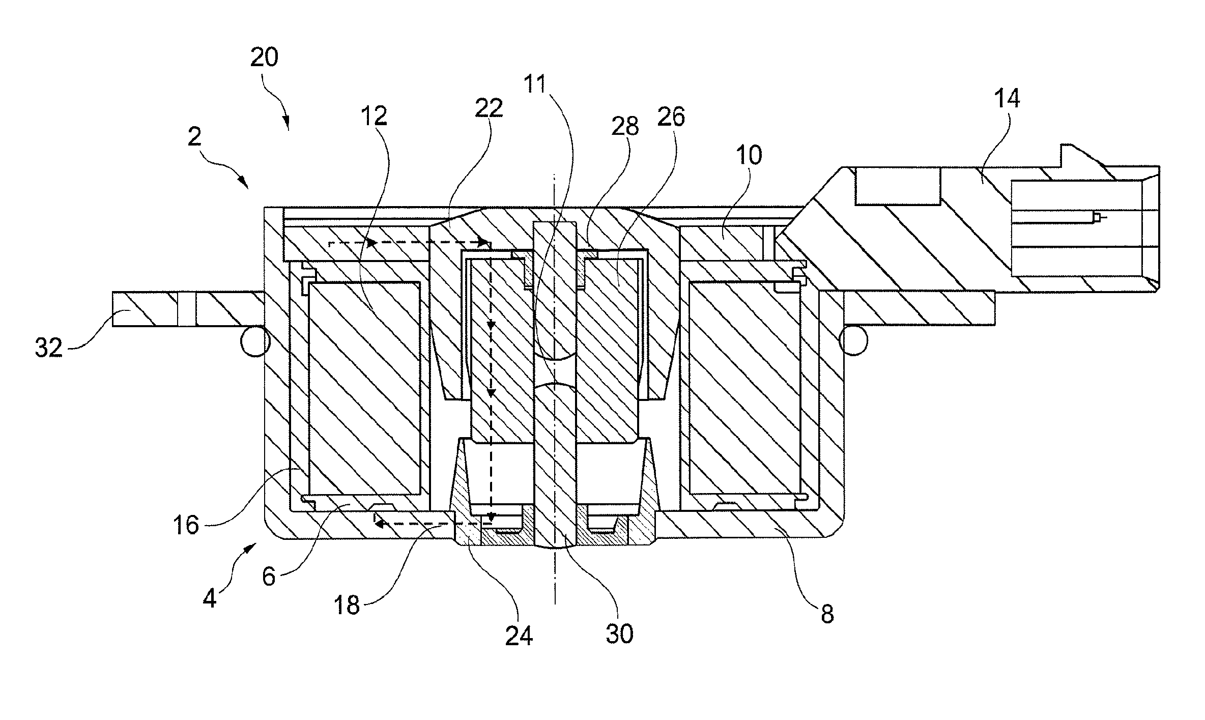
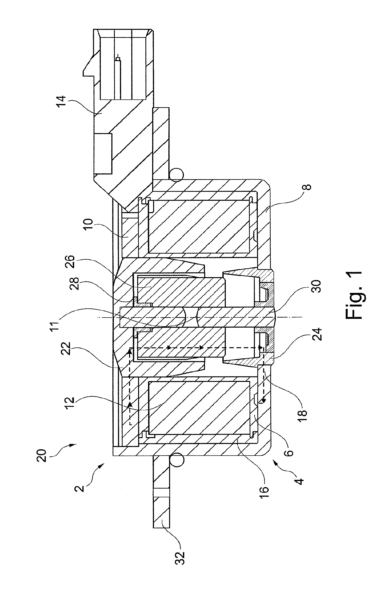
[0030]FIG. 1 shows a longitudinal cross-section of a solenoid 2 comprising a coil 4. The solenoid 2 can be configured as a hydraulic directional valve in a central valve and arranged radially within an inner rotor of a device for variable adjustment of the valve timing in an internal combustion engine.

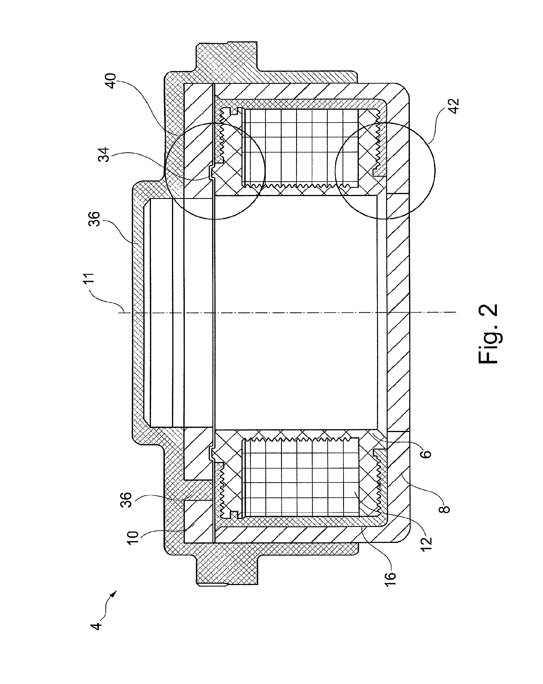
[0031]The coil 4 comprises a cylindrical coil carrier 6, a pot 8 and a yoke disk 10 and is configured rotationally symmetric to an axis of rotation 11. In the coil carrier 6 is embedded a coil wire 12 which can be electrically energized through a plug contact 14. The coil carrier 6, the pot 8 and the yoke disk 10 together define an intermediate space 16 which can be filled with a filler material like plastic so that the coil wire 12 is completely injected over with the filler material.

[0032]The magnetic field 18 which can be generated by the coil wire 12 is transmitted to an axially movable armature 26 via a soft iron circuit 20 comprising a yoke 22, the yoke disk 10, a pole core 24 an...


PUM

PropertyMeasurementUnit
magnetic fieldaaaaaaaaaa
electric energyaaaaaaaaaa
volumeaaaaaaaaaa

Abstract

A coil (4) for a solenoid valve (2) in particular for actuating a camshaft adjuster, including a coil carrier (6) with an underside, a pot (8) with a base on which the underside of the coil carrier (6) is placed and with a wall which forms an intermediate space (16) with respect to the coil carrier (6), and a yoke disk (10) which is placed on the pot (8) with coil carrier (6) and which covers the intermediate space (16), wherein the intermediate space (16) is open via a flow gap (34) between the yoke disk (10) and the coil carrier (6) and / or between the yoke disk (10) and the pot (8) and is provided for receiving a filler (36). The flow gap (34) is formed for the hardening of the filler (36).

Description

[0001]The invention concerns a coil for a solenoid in particular for actuating a camshaft adjuster, a solenoid in particular for actuating a camshaft adjuster and a method for manufacturing a coil for a solenoid.BACKGROUND[0002]A solenoid is an actuator which, in particular by a corresponding actuation, can adjust the through-flow of a fluid, for example, an oil. For example a slide is moved in a solenoid by a tappet that is controlled by a magnetic field excited through electric energy.[0003]The slide of the solenoid is usually placed on the tappet that is connected to an armature of the solenoid. The armature is moved relative to a yoke disk. For this purpose, the yoke disk bundles the magnetic field that is excited by the coil and transmits this via a pole shoe to the armature.[0004]In a solenoid of the pre-cited type, the coil has to be packaged in a leak-free manner. For this purpose, the coil, as shown for example in WO 2010 / 060690, comprises a cylindrical coil carrier compris...

Claims


Application Information

Patent Timeline
Patent Type & Authority Patents(United States)
IPC IPC(8): H01F27/02H01F7/16H01F41/12H01F7/128H01F38/00F01L1/34F01L1/344
CPCH01F38/00F01L1/34H01F7/128H01F7/1607H01F27/02H01F41/127F01L2001/3443Y10T29/4902F01L2001/34433F01L2001/34479F01L2301/00F01L2303/00
Inventor HOPPE, JENSKONIAS, STEFANWUNDERLICH, UWEBAIER, RICHARD
Owner SCHAEFFLER TECH AG & CO KG
Why Eureka
Try Eureka