Control system for a synchronous machine and method for operating a synchronous machine

a control system and synchronous machine technology, applied in the direction of dynamo-electric converter control, dynamo-electric gear control, model/simulation control, etc., can solve the problem of reducing said anisotropy, rotor position information cannot be extracted or at least not extracted with sufficient reliability from data, etc. problem, to achieve the effect of improving method accuracy, efficient synchronous machine operation, and facilitating finding balan

Active Publication Date: 2016-09-13
ROBERT BOSCH GMBH
View PDF9 Cites 4 Cited by
  • Summary
  • Abstract
  • Description
  • Claims
  • Application Information

AI Technical Summary

Benefits of technology

[0008]A concept of the present invention is to expand the application range of sensorless methods for determining the rotor angle for synchronous machines, in particular at low rotational speeds. The invention is based on the recognition that the amplitude of system responses generated and determined on the basis of a sensorless method for determining rotor angle can be increased and as a result the reliability and accuracy of the method for determining rotor angle can be improved by means of an adaptation of the operating-point trajectory of a synchronous machine. To this end, the operating-point trajectory of the synchronous machine is adjusted in such a manner that the difference between the d- and q-inductance of the synchronous machine in the rotor-fixed coordinate system is as high as possible. The determination of the operating-point trajectory of the synchronous machine takes place on the basis of a characteristic diagram which is to be determined in advance and concerns all possible 2-tuples of values of useful current in the rotor-fixed coordinate system, in which the amplitudes of the system responses are plotted as contour lines. On the basis of finding a balance between the efficiency of the synchronous machine and a difference between the d- and q-inductance of the synchronous machine which is as high as possible, the operating-point trajectory can be determined as a compromise between the accuracy of the rotor angle determination and the efficiency of the machine operation.
[0009]A significant advantage of proceeding in this manner is that the operating range of the method for determining the rotor angle for the synchronous machine can be expanded. For example, the saturation of the synchronous machine resulting from the feed of useful current can be correspondingly lowered in the range of higher torques, whereby the significance of the rotor position information is increased.
[0011]According to a further embodiment of the method according to the invention, the determining of the operating-point trajectory can take place while taking into account the level of efficiency of the synchronous machine. This facilitates finding a balance between an efficient operation of the synchronous machine and an improvement in the accuracy of the method for determining the rotor angle.
[0012]According to a further embodiment of the method according to the invention, the determining of the operating-point trajectory can take place in such a manner that the determined difference values along the operating-point trajectory are as high as possible and that the level of efficiency of the synchronous machine along the operating-point trajectory does not drop below a predeterminable threshold value. As a result, the operating-point trajectory can be optimized in a boundary value problem as simply as possible.

Problems solved by technology

Depending on the feed of useful current to the synchronous machine, a decrease in said anisotropy may occur at certain operating points so that the rotor position information can no longer be extracted or at least no longer be extracted with sufficient reliability from the data.

Method used


Image

  • Control system for a synchronous machine and method for operating a synchronous machine
  • Control system for a synchronous machine and method for operating a synchronous machine
  • Control system for a synchronous machine and method for operating a synchronous machine

Examples


Embodiment Construction

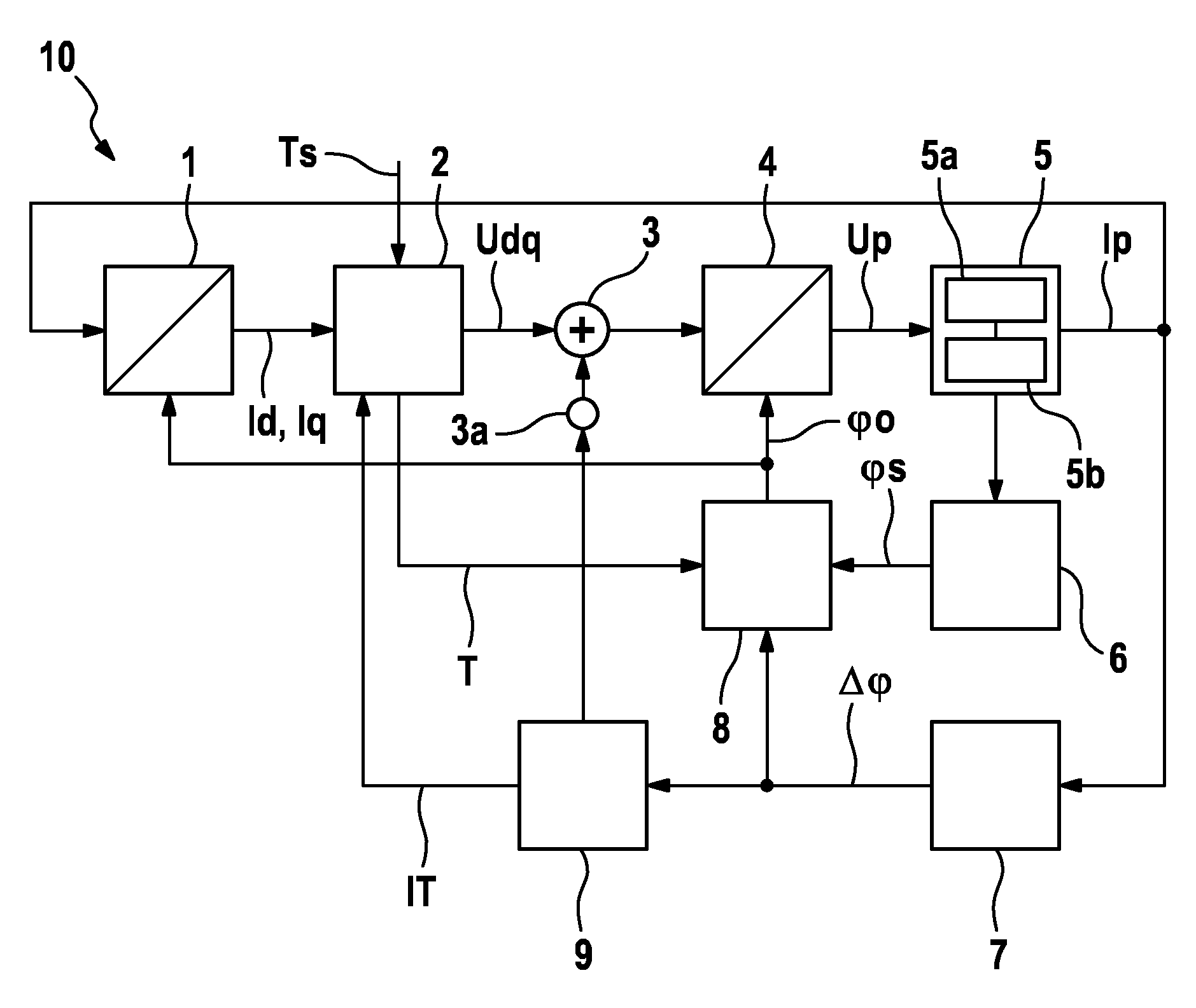
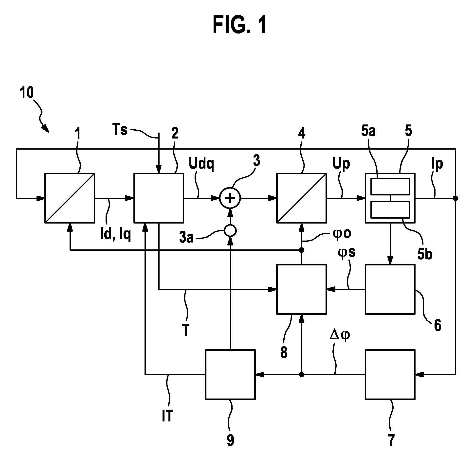
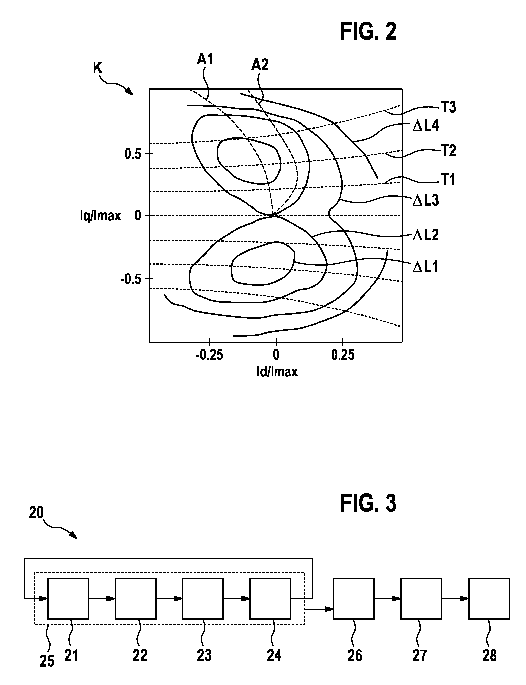
[0020]Identical reference signs generally denote similar or similarly functioning components. The schematic signal and parameter profiles shown in the figures of the drawings are only of an exemplary nature, which for reasons of clarity are configured in an idealized fashion. It goes without saying that signal and parameter profiles that deviate therefrom can result in practice due to deviating boundary conditions and that the depicted signal and parameter profiles are used only to illustrate principles and functional aspects of the present invention.

[0021]Synchronous machines in terms of the present invention are electrical machines, in which a constantly magnetized rotor is driven synchronously by a time-dependent rotating magnetic field in the encompassing field magnet or stator as a result of magnetic interaction; thus enabling the rotor to carry out a movement synchronous to the voltage ratios in the stator. This means that the rotational speed via the number of pole pairs is d...


PUM


Abstract

The invention relates to a method for operating a synchronous machine, comprising the following steps: determining a difference value between the rotor inductance of the synchronous machine in the polar axis direction and the rotor inductance of the synchronous machine in the pole-gap direction for each of a plurality of different 2-tuples from values of useful current adjusted in the rotor-fixed coordinate system of the synchronous machine; preparing a characteristic diagram for the determined difference values in dependence on the 2-tuples of the values of useful current; determining a torque-dependent operating-point trajectory for the 2-tuples of the values of useful current taking into account the magnitude of the determined difference values along the operating-point trajectory to be determined; and operating the synchronous machine according to the determined operating-point trajectory.

Description

BACKGROUND OF THE INVENTION[0001]The invention relates to a control system for a synchronous machine and a method for operating a synchronous machine.[0002]When controlling a synchronous machine, for example in an electrical drive system of an electrically operated vehicle, the acquirement of the relative position of the rotor to the stator of the synchronous machine plays a key role. In order for a synchronous machine to provide a required torque, a rotating electrical field is generated in the stator which rotates synchronously with the rotor. The current angle of the rotor for the feedback control is required for the generating of this field.[0003]An option for determining the rotor angle is to feed test voltage signals into one or a plurality of phases of the synchronous machine and to measure the system response by evaluating the phase currents at the neutral point of the synchronous machine in order to draw conclusions therefrom about the current rotor angle.[0004]The WIPO pat...

Claims


Application Information

Patent Timeline
Patent Type & Authority Patents(United States)
IPC IPC(8): H02P21/00H02P6/14H02P6/18
CPCH02P6/14H02P6/185H02P6/34
Inventor GOETTING, GUNTHERPAULUS, SEBASTIAN
Owner ROBERT BOSCH GMBH
Why Eureka
Try Eureka