Methods, devices, and uses for calculating a position using a global navigation satellite system

a global navigation satellite and receiver technology, applied in the field of global navigation satellite systems, can solve the problems of skewed position computation, reduced calculation accuracy, and greatly limited sky visibility, and achieve the effect of high probability of error

Active Publication Date: 2016-09-20
ARIEL UNIV RES & DEV
View PDF10 Cites 5 Cited by
  • Summary
  • Abstract
  • Description
  • Claims
  • Application Information

AI Technical Summary

Benefits of technology

[0037]In some embodiments, the finding a solution comprises finding a solution which satisfies a maximal number of the inequalities in the set of surface inequalities. In some embodiments, the finding a solution includes assigning a confidence value to each inequality in the set of surface inequalities and finding a solution which maximizes the confidence of satisfied surface inequalities of the set of surface inequalities.
[0047]In some embodiments, the defining comprises defining as the contour edge points specific ones of the locations for which the distance function is greater than a predetermined threshold. In some embodiments, the methods and devices also include, following the finding locations and prior to the defining the locations as contour edge points, eliminating ones of the locations for which there is a high probability of error.
[0050]According to some embodiments, the defining height comprises defining the height to satisfy a maximal number of the plurality of constraints. In some embodiments, the defining height includes assigning a weight to each of the plurality of constraints and computing the height to maximize the weight of satisfied ones of the plurality of constraints. According to some embodiments, the classifying comprises using signal strength classification. In accordance with some aspects of an embodiment of the teachings herein, there are provided methods and devices for transmitting a three-dimensional representation of an area, to a GNSS receiver, for improving calculation, including:

Problems solved by technology

When the line of sight to a number of satellites is blocked, calculated position accuracy may decrease.
For example, in many cities, such as downtown Manhattan, the tall buildings or other obstacles form an urban canyon where sky visibility is greatly limited.
Therefore, a narrowly available sky which allows a GNSS receiver to have a line of sight to less than four satellites, leads to a skewed position computation, or, in the worst case, an inability of the receiver to compute its location.
Moreover, objects such as building walls may reflect a signal from a satellite towards the receiver, leading to a mistaken pseudorange calculation.
As a result of the presence of tall buildings and other obstacles, a receiver in urban areas often provides a position circle with a large radius reflecting a greater error in a position calculation.
Blocked lines of sight and signal reflections in an urban area may lead to estimated errors in position calculation of a few tens of meters, and in some instances even up to hundreds of meters.
In some such cases the GNSS receiver is not able to calculate a position at all.
Thus, the location of the GNSS receiver can be limited by matching a road map of the terrain to the proposed position region, and thereby limiting the possible location of the GNSS receiver to areas of the proposed position region that correspond to roads.
However, one of the disadvantages of dead-reckoning is that new values are calculated using previous values, and therefore errors and uncertainty regarding the calculated values will accumulate over time.

Method used


Image

  • Methods, devices, and uses for calculating a position using a global navigation satellite system
  • Methods, devices, and uses for calculating a position using a global navigation satellite system
  • Methods, devices, and uses for calculating a position using a global navigation satellite system

Examples


Embodiment Construction

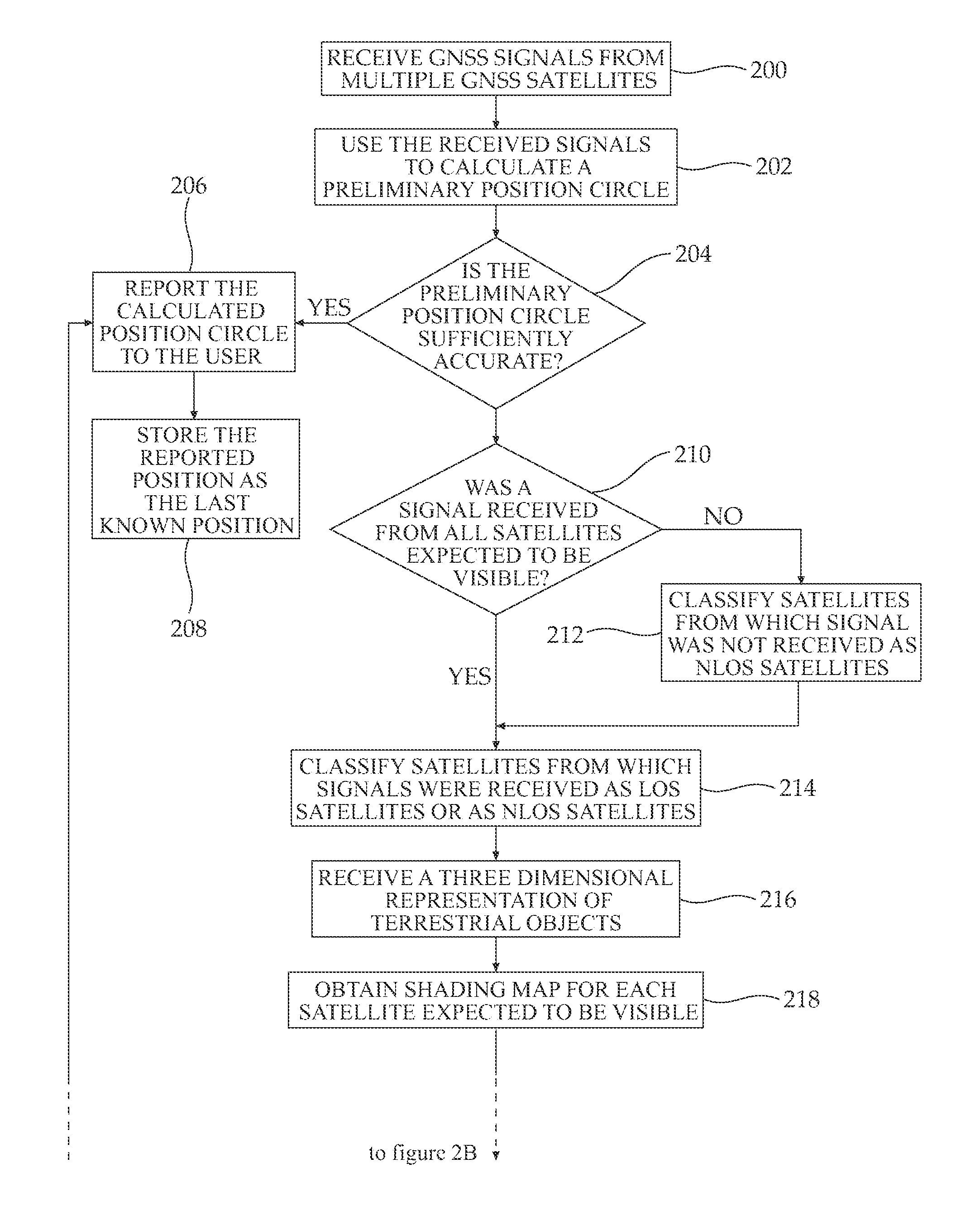
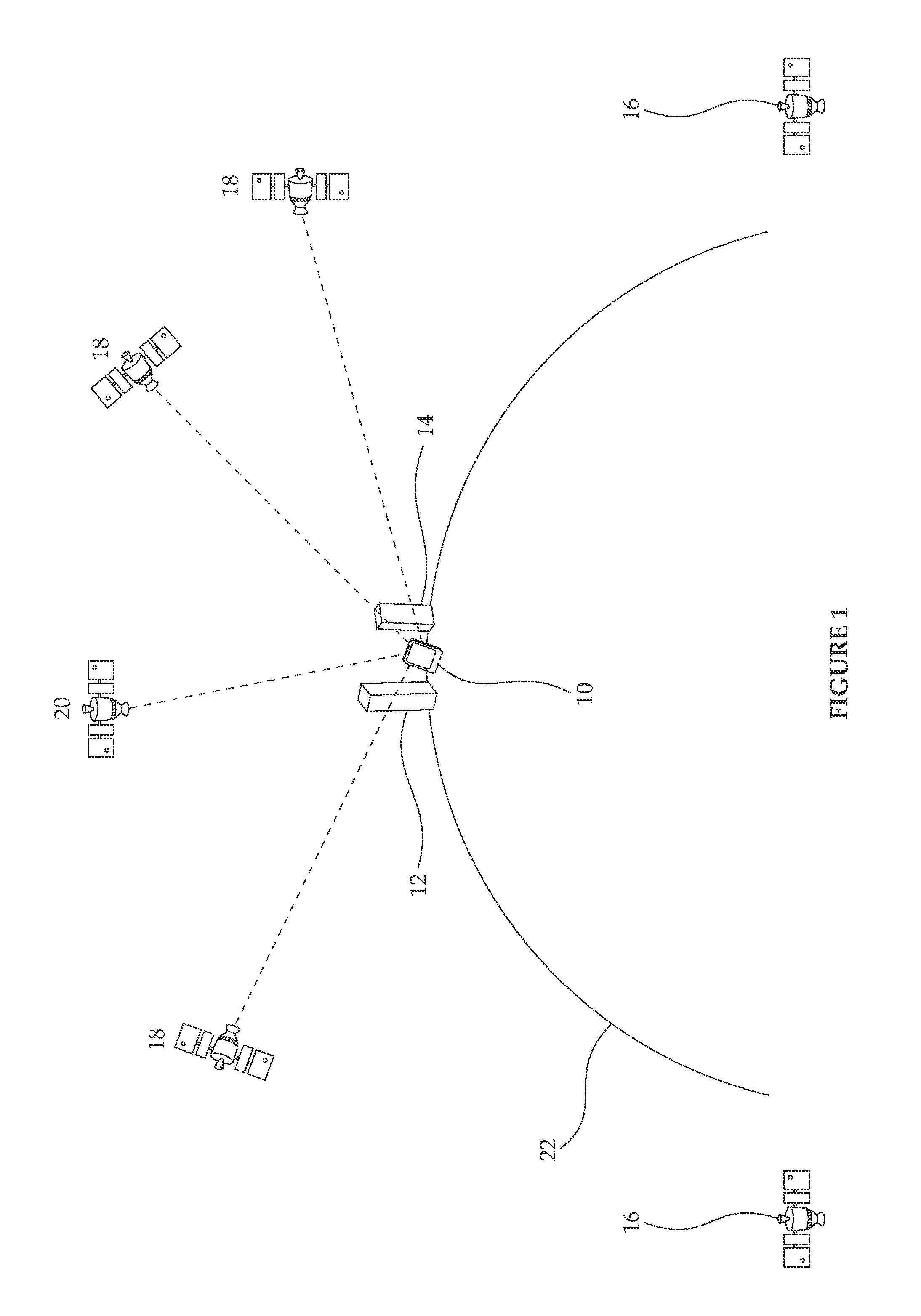
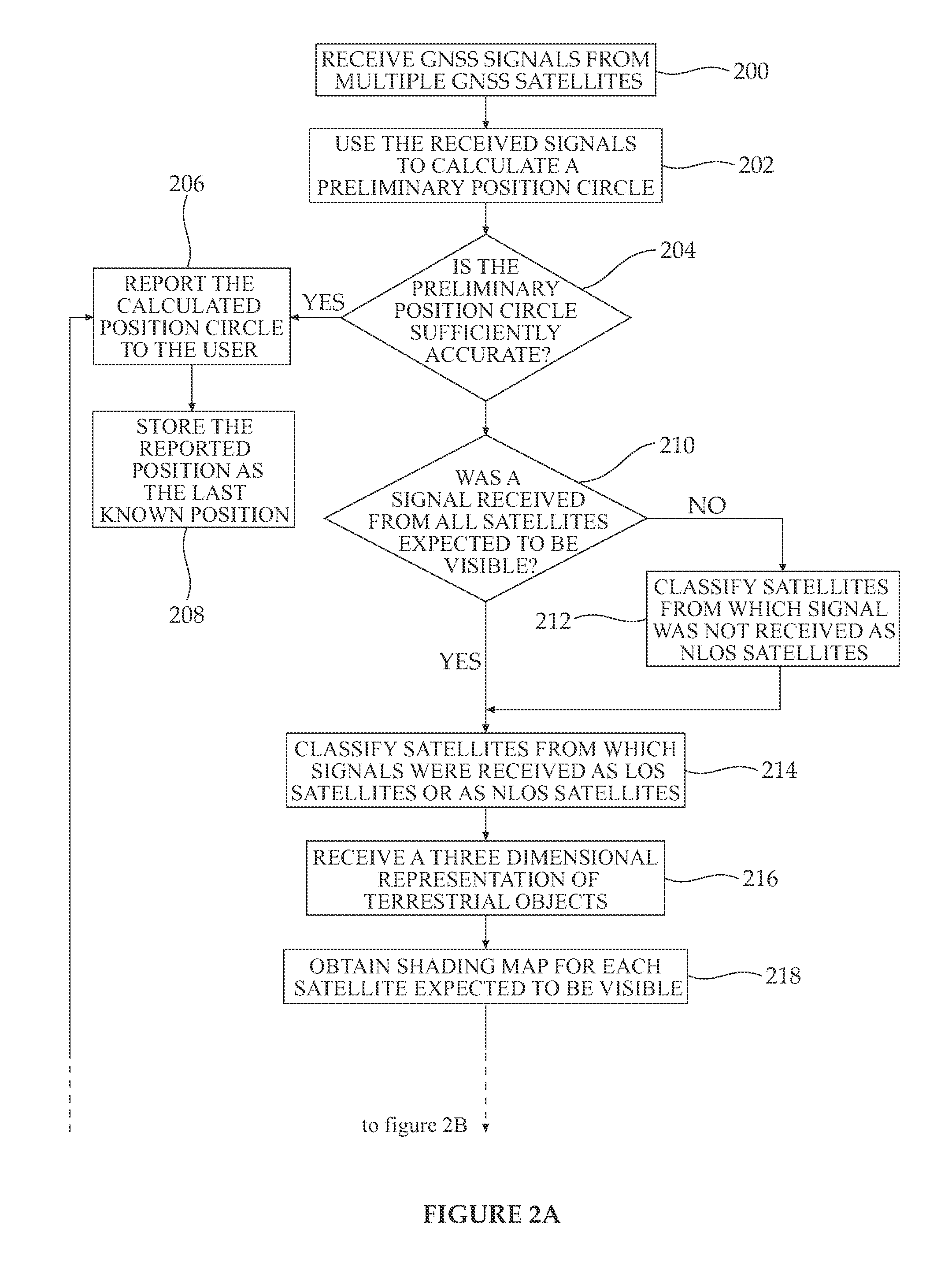
[0071]The invention, in some embodiments, relates to the field of global navigation satellite systems, and more particularly to the field of methods and devices for improving accuracy of position determination by receivers of global navigation satellite systems. Some embodiments of the invention relate to methods for calculating the position of a GNSS (Global Navigation Satellite System) receiver, including:[0072]receiving a plurality of signals from a first plurality of GNSS satellites;[0073]calculating a region in which a GNSS receiver is located based on at least some of the received signals;[0074]for each satellite in a second plurality of GNSS satellites, classifying whether:[0075]the satellite is a line-of-sight (LOS) satellite, having a line of sight to the GNSS receiver; or[0076]the satellite is a non-line-of-sight (NLOS) satellite, not having a line of sight to the GNSS receiver;[0077]obtaining at least one three-dimensional representation of an area including the region;[0...


PUM


Abstract

The invention, in some embodiments, relates to the field of global navigation satellite systems, and more particularly to the field of methods and devices for improving accuracy of position determination by receivers of global navigation satellite systems. Some embodiments of the invention relate to methods for generating a three-dimensional (3-D) representation of an urban area by a receiver of a global navigation satellite system using blocked lines of sight to satellites of the system. Additional embodiments of the invention relate to methods for transmitting a three-dimensional (3-D) representation of an urban area by a receiver of a global navigation satellite system for improving calculation of location by the global navigation satellite system receiver.

Description

RELATED APPLICATIONS[0001]This Application is a national phase of, and claims priority from, PCT Application No. PCT / IB2011 / 055899, filed on Dec. 22, 2011, which claims priority from U.S. Provisional Application No. 61 / 426,541, filed Dec. 23, 2010, both of which applications are hereby incorporated by reference as if fully set forth herein.FIELD AND BACKGROUND OF THE INVENTION[0002]The invention, in some embodiments, relates to the field of global navigation satellite systems, and more particularly to the field of methods and devices for position determination by receivers of global navigation satellite systems.[0003]The invention, in some embodiments, relates to the field of urban mapping systems, and more particularly to the field of methods for generating a three-dimensional (3-D) representation of an urban area using a receiver of a global navigation satellite system.[0004]Global Navigation Satellite Systems (GNSS) provide autonomous geo-spatial positioning, typically including ...

Claims


Application Information

Patent Timeline
Patent Type & Authority Patents(United States)
IPC IPC(8): G01S19/42G01S19/31G01S19/38G01S19/23G01S19/50G01S19/40G01C21/20
CPCG01S19/31G01C21/20G01S19/23G01S19/40G01S19/50G01S19/39G01S19/27G01S19/42
Inventor BEN-MOSHE, BOAZLEVI, HAREL
Owner ARIEL UNIV RES & DEV
Why Eureka
Try Eureka