
Power back-off for limiting emissions and power consumption

a technology of power back-off and emission limitation, applied in the field of powerline communication, can solve the problems of increasing the transmission time required for transmitting a set amount of information, the cost of reducing transmission power, and the antenna used as an antenna that generates significant radio frequency (rf) emissions, so as to achieve the desired rate of communication. the effect of very low

Inactive Publication Date: 2016-10-04
QUALCOMM INC
View PDF6 Cites 1 Cited by
  • Summary
  • Abstract
  • Description
  • Claims
  • Application Information

AI Technical Summary

Benefits of technology

The patent text describes techniques for reducing electrical emissions and improving the energy efficiency of powerline communication networks. These techniques involve reducing transmission power to a minimum level to achieve a desired rate of communication for each application. This can increase network utilization and decrease transmission time, thus improving network performance. The patent also includes a method for establishing a minimum throughput threshold to prevent excessive consumption of channel capacity by individual nodes. Overall, the techniques facilitate better performance and reliability of powerline communication networks.

Problems solved by technology

Furthermore, the electrical wiring can serve as antennas that generate significant radio frequency (RF) emissions (e.g., noise) affecting wireless devices.
In some scenarios, the cost of reducing transmission power is increasing the transmission time required for transmitting a set amount of information (e.g., a frame).
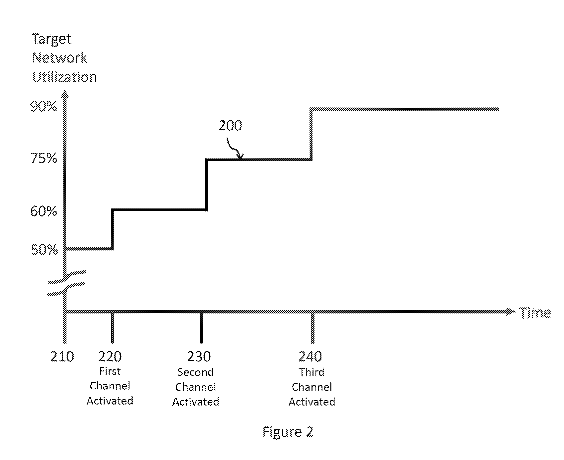
Accordingly, when a PLC device's transmission power is decreased in these scenarios, the PLC device may spend relatively more time transmitting on the transmission medium, which increases network utilization.
In some low priority applications, such as those classified as having best-effort traffic, the desired rate of communication may be very low.

Method used


Image

  • Power back-off for limiting emissions and power consumption
  • Power back-off for limiting emissions and power consumption
  • Power back-off for limiting emissions and power consumption

Examples


Embodiment Construction

)

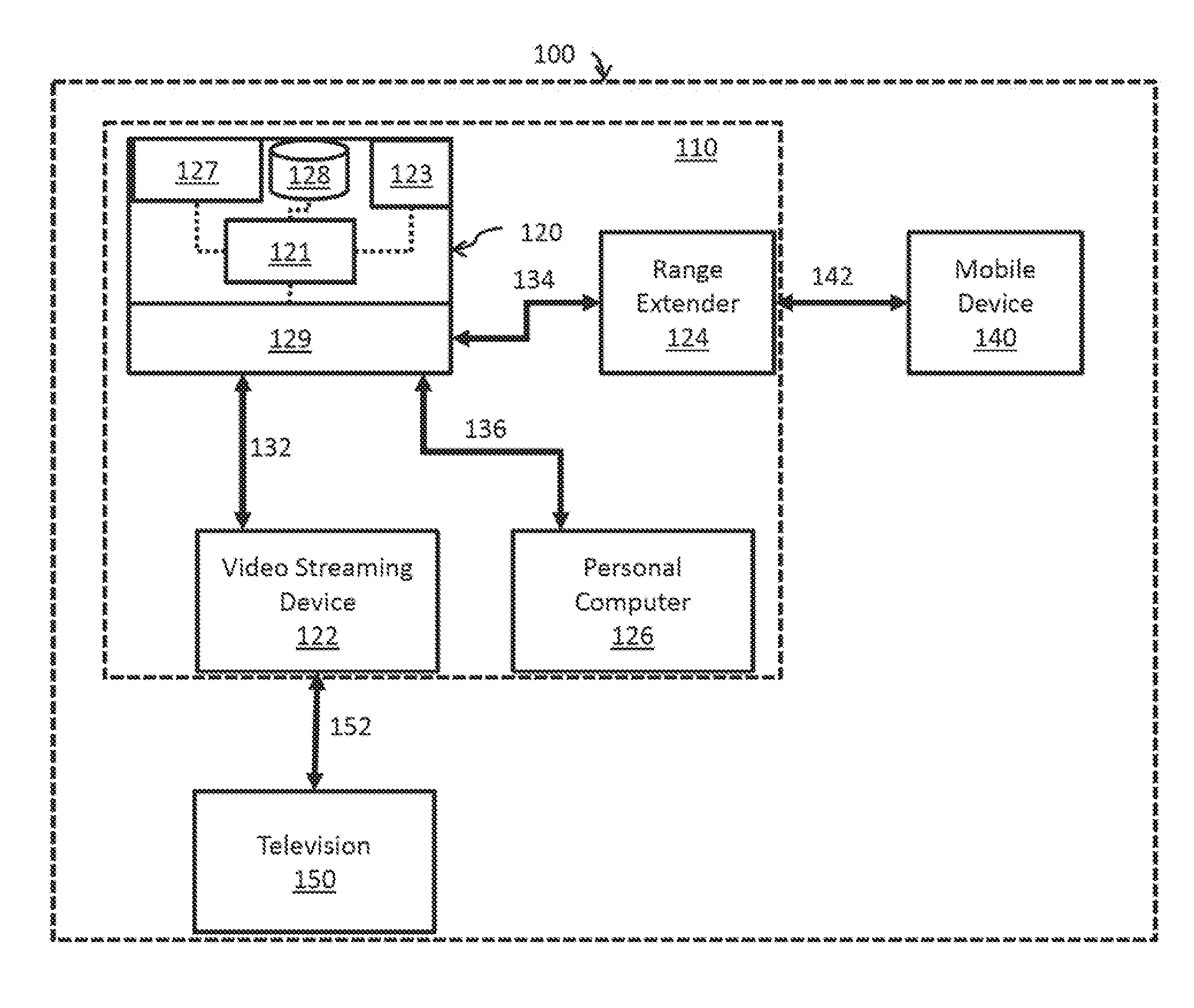
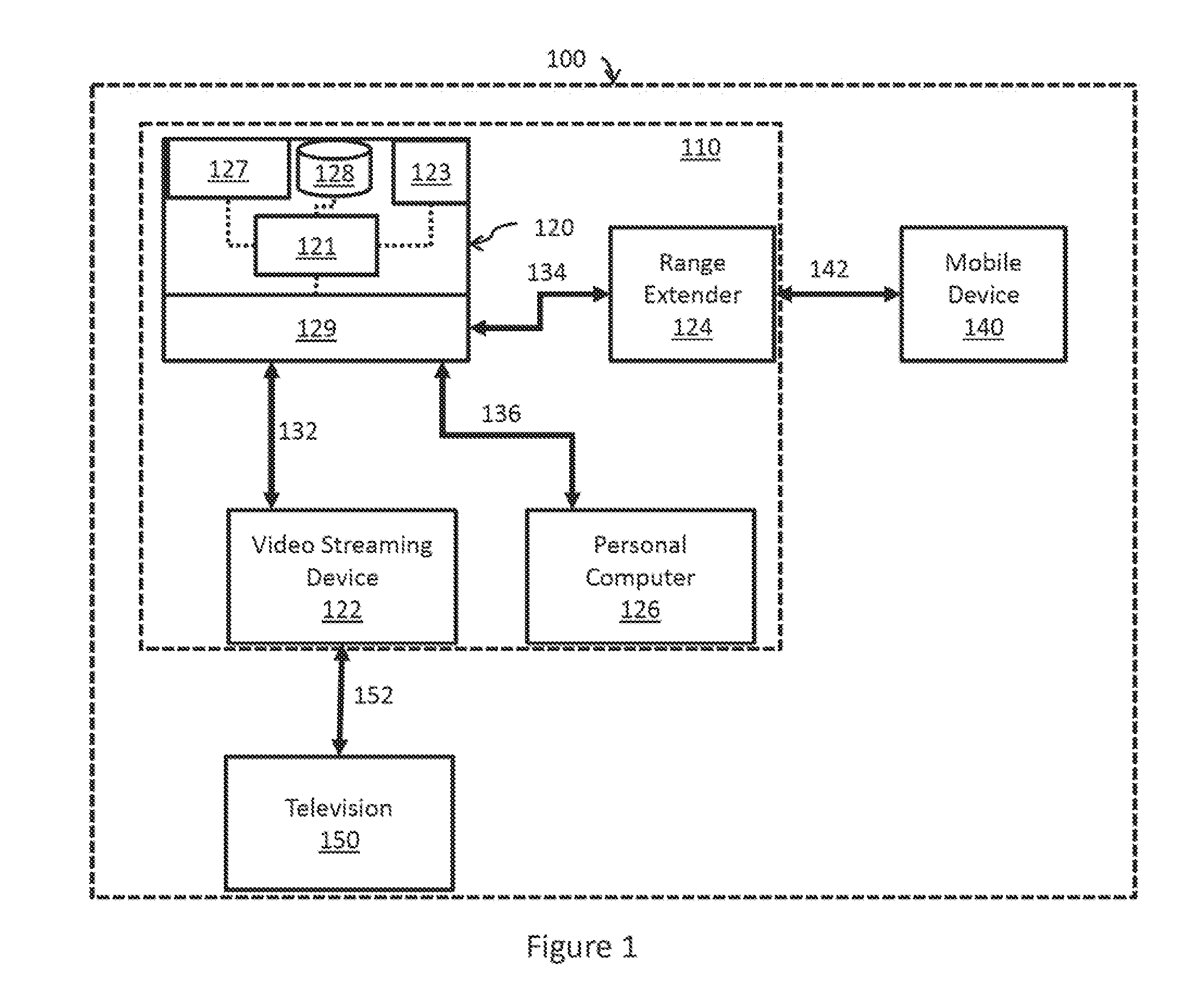
[0019]FIG. 1 shows a block diagram illustrating a system 100 for communicating between powerline communication nodes. The system 100 includes elements traditionally found in a home environment, though the disclosed principles may be applied to powerline communication (PLC) networks deployed in a work place, automobile, or other environment having a powerline infrastructure. The system 100 may comprise an access point 120 that receives connectivity to an external, broader network (e.g., the internet) via a port 127. The connectivity to the external, broader network may be established via a wired connection or a wireless connection, which may use a cellular protocol such as a 2G, 3G, or 4G LTE protocol. The access point 120 may, for example, be an internet gateway router that may comprise a wireless transceiver 123 to provide wireless connectivity (e.g., WiFi) to local devices in addition to the PLC connectivity described below. The access point 120 may additionally or alternatively ...


PUM


Abstract

Powerline communication (PLC) networks allow devices within a home, automobile, or other systems to communicate over existing wired powerline infrastructure. Active PLC networks can affect devices sharing the powerline infrastructure as well as wireless devices through radiated noise emissions. Provided in the present disclosure are exemplary techniques for reducing noise emissions and promoting coexistence of multiple PLC systems and / or non-PLC (e.g., wireless) systems.

Description

BACKGROUND[0001]1. Field of the Disclosure[0002]The present application generally relates to powerline communication (PLC) and, more specifically, to systems and methods for limiting noise emissions and reducing transmission power associated with powerline communication networks.[0003]2. Description of Related Art[0004]Powerline communication networks use existing powerline infrastructure (e.g., the power lines within a home, automobile, or even across multiple homes) to send signals between PLC devices or nodes. For example, a powerline communication network can supplement a home's wired (e.g., Ethernet) and wireless (e.g., WiFi) networks. The bandwidth of powerline communication networks has greatly increased in recent times. For example, some PLC channels are now capable of delivering one gigabit per second (Gbps) speeds, which are sufficient for multiple HD video streams. As a result, powerline communication networks are becoming increasingly practical and prevalent.[0005]Curren...

Claims


Application Information

Patent Timeline
Patent Type & Authority Patents(United States)
IPC IPC(8): H04B3/00H04L12/26H04B3/54H04L12/24
CPCH04B3/54H04L41/0823H04L43/065H04L43/0876
Inventor AFKHAMI, HASSAN KAYWANRAJKOTIA, PURVA RAMESHCHANDRA
Owner QUALCOMM INC
Learn More