Face equipment comprising hose levels placed on the shield support frames of said face equipment

a technology of face equipment and shield support, which is applied in the direction of hydrostatic levelling, mine roof supports, slitting machines, etc., can solve the problems of completely entrapped liquid in the hose and alter the pressure level, so as to reduce the measuring range of the pressure sensor, dampen the hydraulic pressure fluctuations, and minimize the influen

Inactive Publication Date: 2016-10-18
RAG AG
View PDF10 Cites 0 Cited by
  • Summary
  • Abstract
  • Description
  • Claims
  • Application Information

AI Technical Summary

Benefits of technology

[0008]The invention is associated with the advantage that the flexible hose level arranged on individual shield support frames or even on each shield support frame can be used to ascertain the distance between the two ends of the hose, and thus between the roof canopy and floor skid of the shield support frame, based on the height of the liquid column determined through pressure measurement, and to calculate the absolute height of the extended shield support frame between the upper edge of the roof canopy and the lower edge of the floor skid, taking into account the geometrically fixed position of the hose ends on the roof canopy and floor skid. Since the inclination measuring device arranged on the roof canopy as described in the invention provides additional information about the transverse inclination and longitudinal inclination of the roof canopy, and hence about its location in the room, the trigonometric calculation formulas can be used to convert the result obtained from height determination for the extended shield support frame into the height perpendicular to the stratification for the shield support frame, and hence into the height perpendicular to the stratification for the face opening between the hanging wall and footwall.
[0009]With respect to the design of the flexible hose level, a first embodiment of the invention provides that the flexible hose level is designed as a closed flexible hose level with a pressure-filled hose that is closed on both sides and connected to a pressure accumulator. The advantage to a flexible hose level closed on both sides essentially lies in the fact that a barometric correction is not needed, and that degassing-induced density changes in the liquid (for example, dissolved air) play a lesser, and hence negligible, role due to the elevated pressure level in the pressure-filled hose. For example, a disadvantage to the closed flexible hose level is that the liquid contained in the hose is completely chambered. As a result, pinching or temperature changes of the hose and liquid alike can alter the pressure level. In order to minimize this influence, a pre-stressed pressure accumulator blister with a pre-stressed gas that acts against the liquid column is connected to the hose. This also dampens hydraulic pressure fluctuations, e.g. caused by vibrations, while at the same time protecting the pressure sensors against possible pressure spikes. As a consequence, the measuring range of the pressure sensors can also be reduced to improve measuring accuracy.
[0010]As an alternative, it can be provided that the flexible hose level be configured as a flexible hose level open on one side, with a hose connected to an overflow forming the highest point of the flexible hose level, for example in the form of an overflow basin arranged on the shield support frame. The advantages to such a flexible hose level open on one side here lie in the fact that a simple hydrostatic pressure / height determination is present. Hose pinching or temperature-induced changes in internal pressure are prevented from influencing the measurement, and there is also only a slight sensitivity to dynamic influences in the form of mechanical oscillations. The disadvantage is that a barometric correction is required for precision measurements. In addition, problems may be encountered with respect to the arrangement of the open flexible hose level in the shield support frame, since the open end of the hose with the overflow basin must always lie at the highest location. This may require reconstruction work given the variable operating conditions that cannot be ruled out during underground mining operations. A flexible hose level overflow or refilling must also be ensured to achieve a properly operating flexible hose level.

Problems solved by technology

For example, a disadvantage to the closed flexible hose level is that the liquid contained in the hose is completely chambered.
As a result, pinching or temperature changes of the hose and liquid alike can alter the pressure level.

Method used


Image

  • Face equipment comprising hose levels placed on the shield support frames of said face equipment
  • Face equipment comprising hose levels placed on the shield support frames of said face equipment
  • Face equipment comprising hose levels placed on the shield support frames of said face equipment

Examples


Embodiment Construction

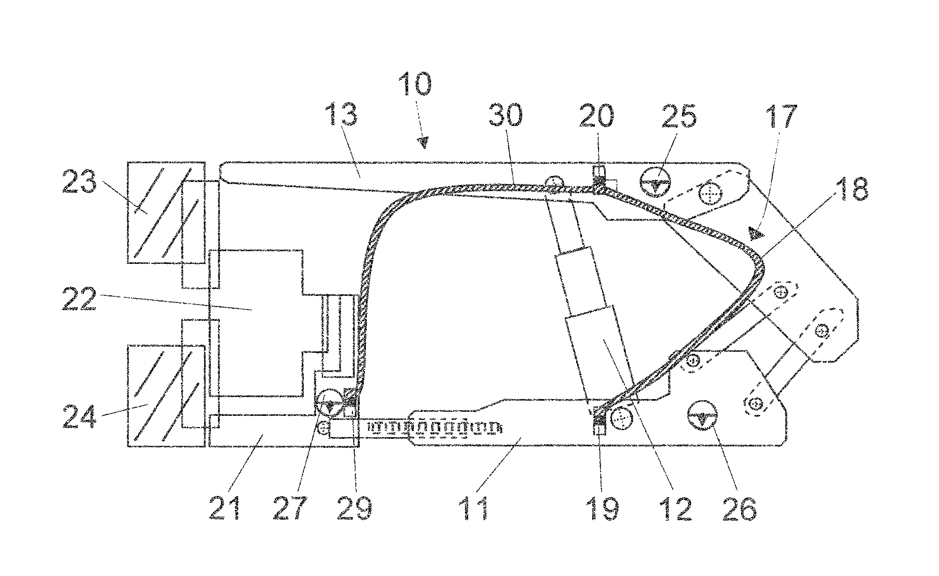
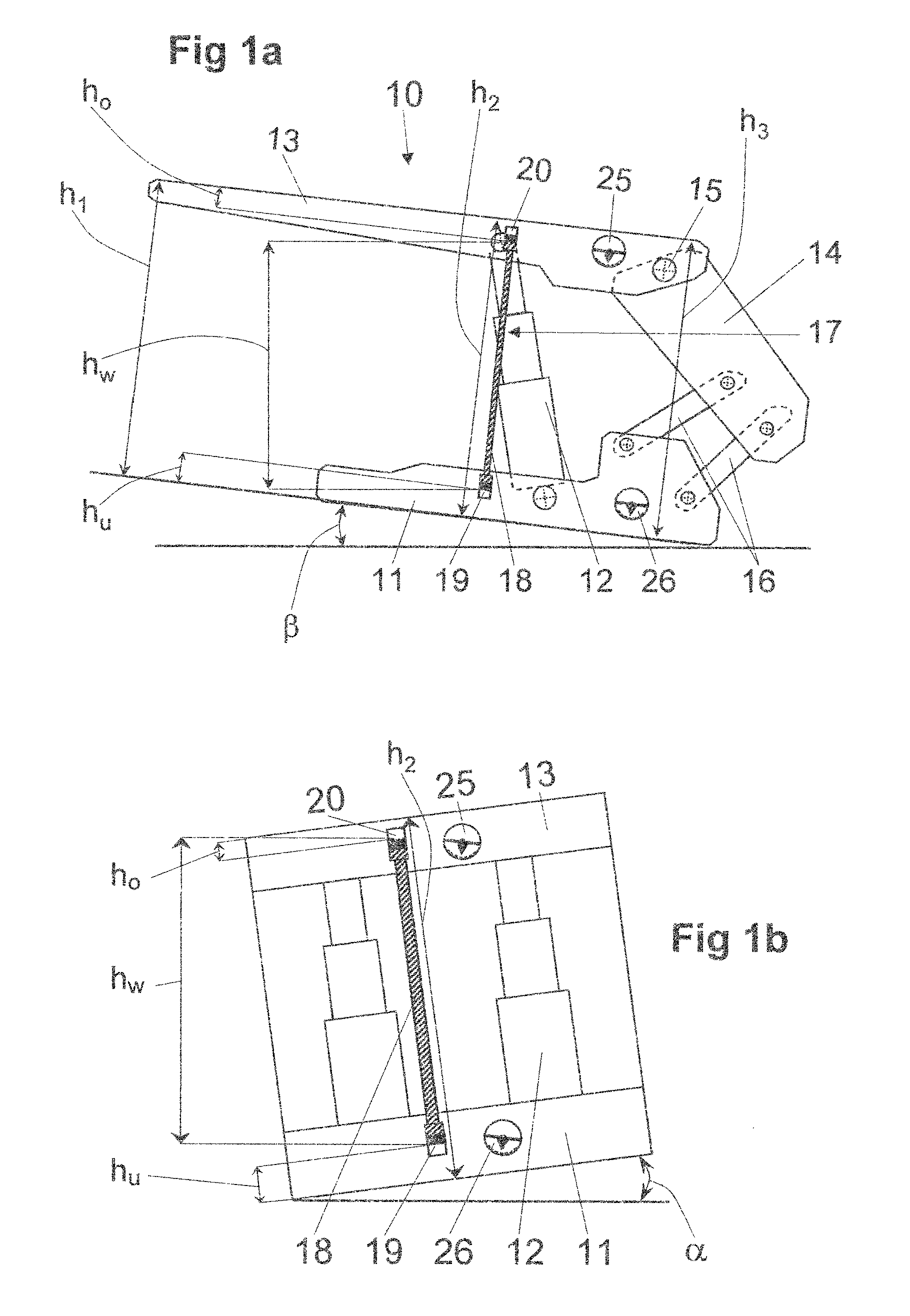
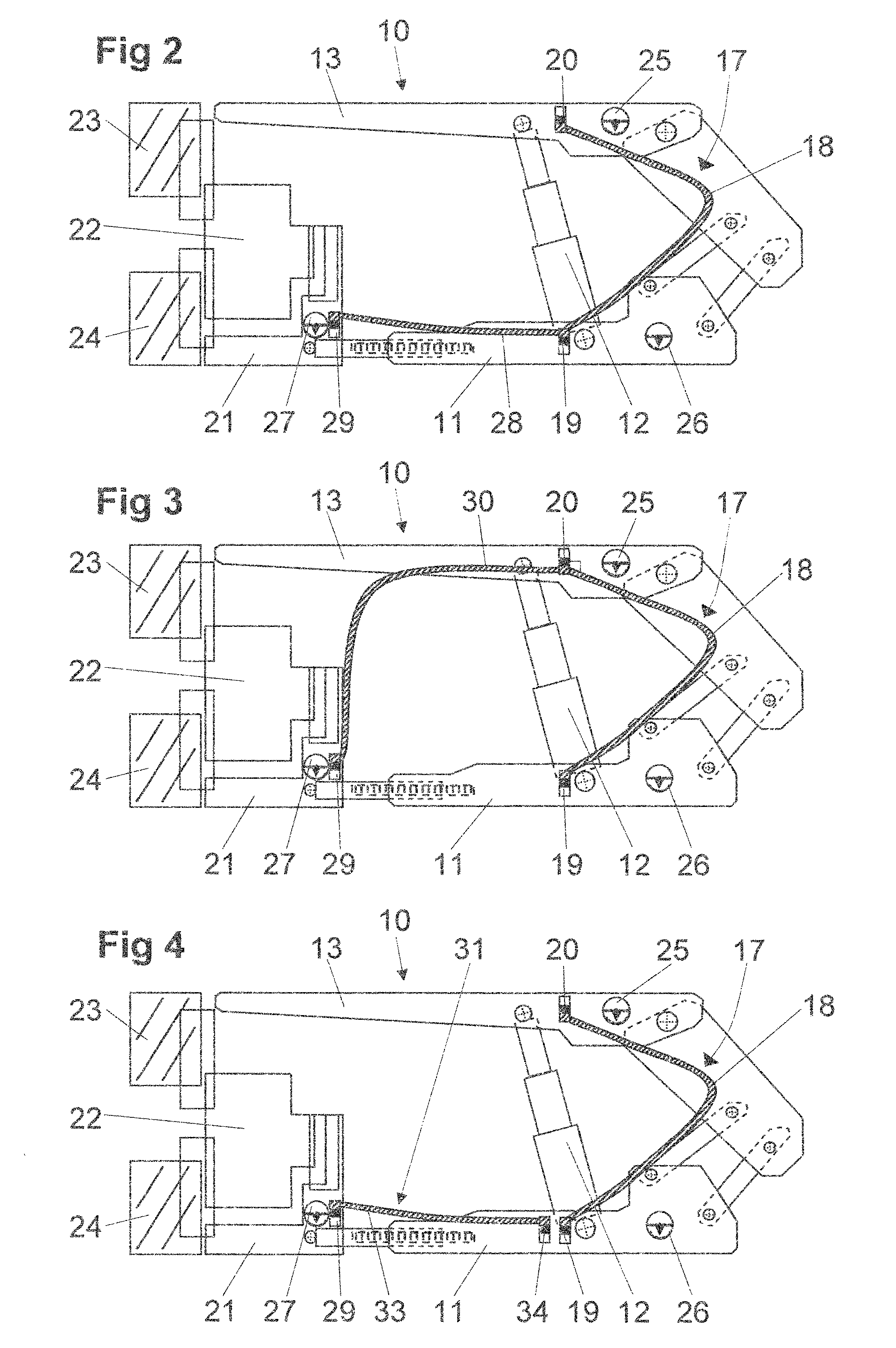
[0029]The shield support frame 10 schematically depicted on FIG. 1 initially encompasses a floor skid 11, which has attached to it two parallel arranged props 12, of which only one prop can be discerned on FIG. 1a, and whose upper end bears a roof canopy 13. While the roof canopy 13 protrudes at its front (left) end toward an extraction machine not shown on FIG. 1a but visible from FIGS. 2 to 4, the rear (right) end of the roof canopy 13 has secured to it a gob shield 14 by means of a joint 15, wherein the gob shield 14 is supported by two support connections rods 16 resting on the floor skid 11 in the side view.

[0030]Arranged on the shield support frame 10 is a flexible hose level 17 with a hose 18 laid between the roof canopy 13 and floor skid 11, whose upper end is situated on the roof canopy 13, and whose lower end is situated on the floor skid 11. Located at both ends are respective pressure sensors, specifically a lower pressure sensor 19 at the end of the hose 18 arranged on ...


PUM


Abstract

A face equipment for mechanical extraction in longwall mining, in particular in the underground hard coal mining industry, includes a face conveyor (21) arranged along the coal face, an extraction mechanism (22) that can be moved along the face conveyor (21), and shield support frames (10) fastened at an angle to the face conveyor (21). In order determine the shield height of the extended shield support frame (10) corresponding to the face opening height, a flexible hose level (17) with a liquid-filled hose (18) is installed between the roof canopy (13) and floor skid (11) of individual shield support frames (10), and a pressure sensor (19) is arranged on the skid-side end of the hose (18). An inclination measuring device (25) is arranged on the roof canopy (13), and the pressure sensor (19) and inclination measuring device (25) are connected to an analyzing and control unit.

Description

[0001]The instant application should be granted the priority date Apr. 2, 2012, the filing date of the international patent application PCT / EP2012 / 055940.BACKGROUND OF THE INVENTION[0002]The invention relates to a face equipment for mechanical extraction in longwall mining, in particular in the underground hard coal mining industry, comprising a face conveyor arranged along the mining wall, an extraction means that can be moved along the face conveyor, and shield support frames supported on the face conveyor at an angle thereto.[0003]WO 2009 / 103303 describes a face equipment with the aforementioned features along with a method for controlling such a face equipment. To this end, the above publication explains in detail that automating such a controller for the face equipment generally depends on knowing where the face equipment is positioned in the room, but especially on knowing the respective height of the face opening that exists in the region of the front end of the roof canopy o...

Claims


Application Information

Patent Timeline
Patent Type & Authority Patents(United States)
IPC IPC(8): E21D23/16E21D23/26E21C31/08E21D23/12E21C35/24E21C35/04G01C5/04
CPCE21D23/26E21C31/08E21C35/04E21C35/24E21D23/12G01C5/04E21D23/16E21D23/0004E21D23/0409
Inventor JUNKER, MARTINMOZAR, ARMIN
Owner RAG AG
Why Eureka
Try Eureka