
Long shaft propeller controller and bearing seal protector

a technology of propeller controller and bearing seal protector, which is applied in marine propulsion, vessel construction, propulsive elements, etc., can solve the problems of unsatisfactory prior art inboard and outboard motors, propeller easily becoming tangled in vegetative matter, and rounded boat hulls and deep propeller arrangements used in open waterways are no longer effective or useful, etc., to achieve low mass and inertia, improve seal protection, and facilitate manual control

Active Publication Date: 2016-10-25
GILK ARLON J +1
View PDF4 Cites 1 Cited by
  • Summary
  • Abstract
  • Description
  • Claims
  • Application Information

AI Technical Summary

Benefits of technology

The invention provides a long shaft propeller that automatically seeks the water surface and protects it from damage. It also has low mass and inertia and improves the protection of seals to increase the lifespan of bearings. Additionally, it reduces displacement of the boat so that it can track in a flat position and operate in shallower waters without sacrificing speed.

Problems solved by technology

Unfortunately, when traversing smaller or shallower bodies of water, such as swamps, creeks and streams, the rounded boat hulls and deep propeller arrangements used in open waterways are no longer effective or useful.
The hull runs deeper than some sections of these smaller waterways, or obstacles present therein, and the propeller readily becomes tangled in vegetative matter, or, worse, may be destroyed by the obstacles.
Particularly for those applications where the water is either shallow or filled with many obstacles, the prior art inboard and outboard motors are unsatisfactory.
An important issue for shallow water application is the location and inertia of the prop in the water.
As aforementioned, there are many shallow obstacles.
When an obstacle is encountered, the boat will typically strike the obstacle first.
Desirably, the boat will be deflected, and, owing to the large area and significant framework typically found in a boat of this nature, the boat will be unharmed or sustain only cosmetic damage.
The propeller will next encounter the hazard.
Furthermore, the deeper the prop runs in the water, the more obstacles that will be encountered.
This proves to be both difficult and physically taxing.
Another limitation of the prior art has to do with the reliability and durability of these long shaft motors.
In addition to the obstacles that can bend or destroy parts, the operation in shallow waters virtually ensures rapid wear and destruction of the seals that protect the bearings needed to support the rotating shaft.
Unfortunately, as sand, dirt or other matter enters into the seals, the seals are rapidly destroyed.
Once the seal is destroyed, the bearings are then exposed to excessive water flow and the very same matter that destroyed the seal.
Consequently, once the seal fails, the life expectancy of the bearing is greatly reduced.
Heretofore, commercially used seals and bearings have had a very short life expectancy, in some of the more extreme cases requiring replacement after only a few hours of operation in shallow, sandy-bottom waterways.

Method used


Image

  • Long shaft propeller controller and bearing seal protector
  • Long shaft propeller controller and bearing seal protector
  • Long shaft propeller controller and bearing seal protector

Examples


Embodiment Construction

[0027]Manifested in the preferred embodiment, the present invention provides a long shaft propeller that tracks to the surface of the water, and that further provides an extended seal and bearing life, thereby reducing the need for service or likelihood of failure during use.

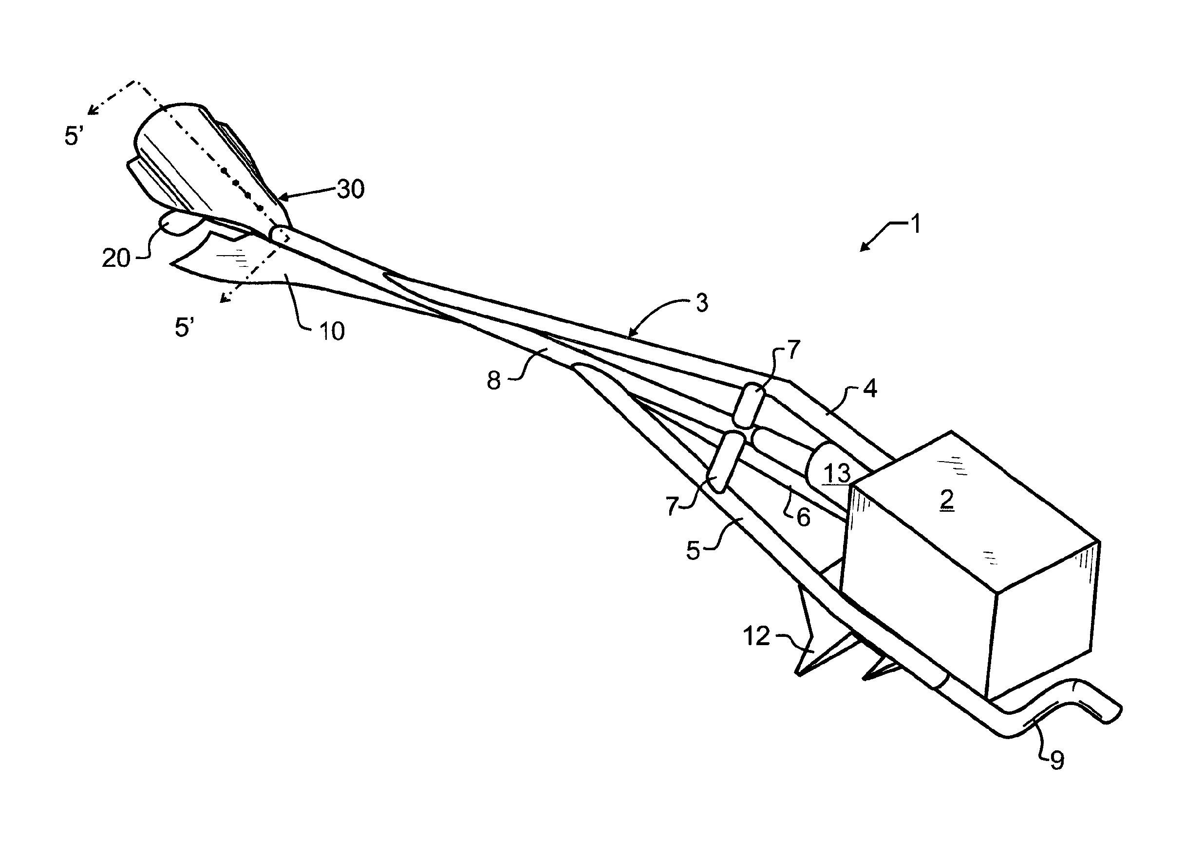
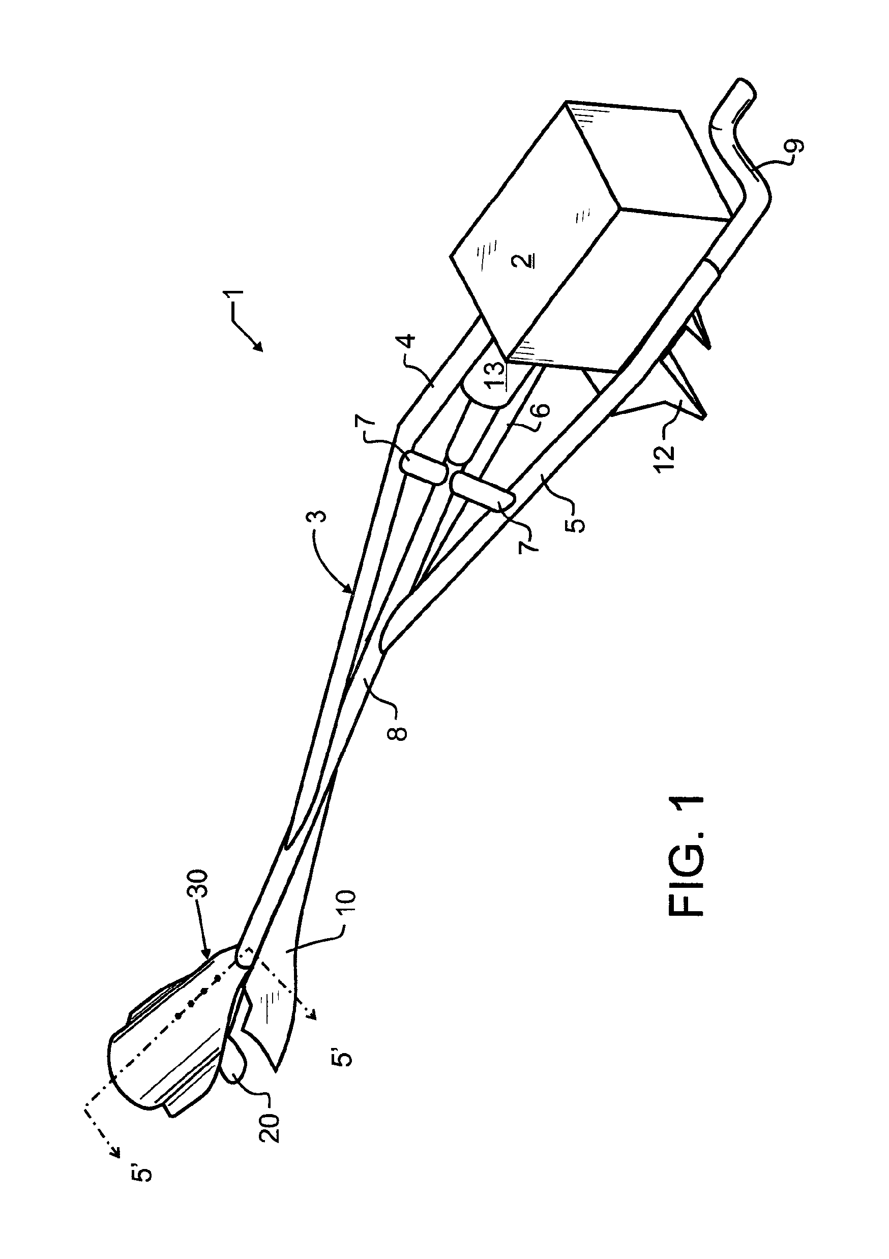
[0028]A preferred embodiment long shaft propeller 1 is illustrated in FIG. 1. A transom mount 12 or suitable equivalent will most preferably be provided for coupling to a water craft such as a flat bottom boat or the like. A source of motive power 2, which will be known to those in the art to include such devices as internal combustion engines, electric motors and other known motive power sources is operatively connected through appropriate linkage, commonly including a universal joint, fasteners and other suitable couplers known in the art, and for exemplary purposes enclosed in safety shield 13, to propeller shaft 70 (visible in FIGS. 5 and 6). Shaft 70 passes through casing 8 to propeller 20. A framework 3 is...


PUM


Abstract

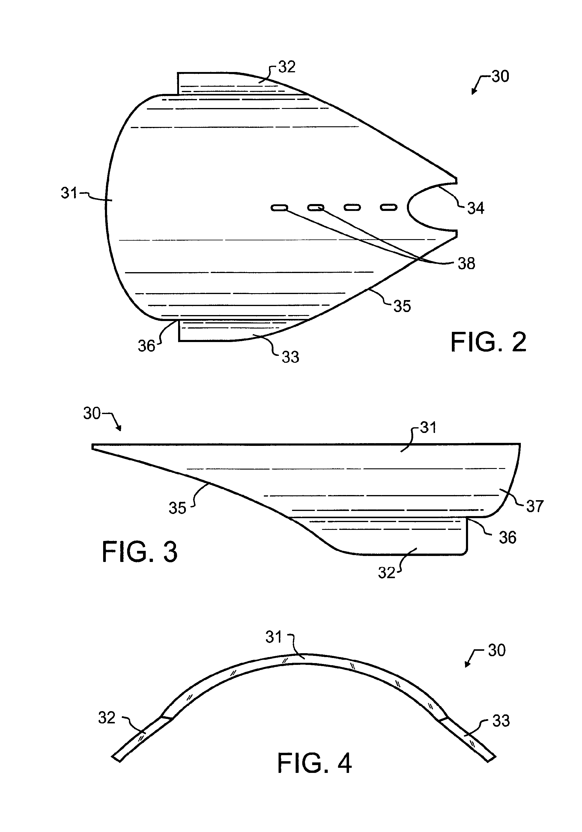
A marine propulsion system for shallow waters, swamps, savannahs and the like includes a rotating propeller shaft supporting a propeller. An anti-cavitation body defines a partial cylinder having a longitudinal axis adjacent to the propeller. The propeller generates a vacuum between the anti-cavitation body and a surface of a water body. First and second wings adjacent to edges of the anti-cavitation body are generally planar and operatively angled towards the bottom of a water body. The first and second wings are adjusted to run below the water body surface and seal the anti-cavitation body to maintain generated vacuum. A first thread is cut in a first helical direction at an end of the rotating propeller shaft adjacent the propeller, and slightly more distal therefrom a second thread is cut in a second helical direction opposed to the first thread helical direction. The second thread drives matter away from the bearing.

Description

CROSS REFERENCE TO RELATED APPLICATIONS[0001]This application is a Continuation of U.S. patent application Ser. No. 13 / 398,864 filed Feb. 17, 2012 and granted as U.S. Pat. No. 8,911,272 on Dec. 16, 2014 co-pending herewith, of like title and inventorship, the contents which are incorporated herein by reference in entirety.BACKGROUND OF THE INVENTION[0002]1. Field of the Invention[0003]The present invention pertains to marine propulsion systems generally, and more specifically to marine propulsion systems utilizing an elongated propeller drive shaft having a housing surrounding the propeller shaft.[0004]2. Description of the Related Art[0005]Modern marine vehicles are most commonly powered by an internal combustion engine mounted within the boat or above the water line adjacent the boat. The mechanical power generated by the engine is transferred through a drive shaft to a water propulsion device such as a propeller. These marine vehicles provide a mode of transportation for traversi...

Claims


Application Information

Patent Timeline
Patent Type & Authority Patents(United States)
IPC IPC(8): B63H1/18B63H1/28B63H1/14B63H20/10B63H5/125
CPCB63H1/18B63H1/14B63H1/28B63H23/321B63H25/42B63H5/14B63H5/165B63H20/34B63H23/36
Inventor GILK, ARLON J.HOESCHEN, LAWRENCE L.
Owner GILK ARLON J
Learn More