
Autostereoscopic display device and drive method

a display device and display device technology, applied in optics, instruments, electrical equipment, etc., can solve the problems of affecting the viewing experience, the viewing position must be fixed, and the barrier arrangement is simple to produce but not light efficient, so as to reduce the number of views, reduce crosstalk, and increase sharpness

Active Publication Date: 2016-10-25
DIMENCO HLDG BV
View PDF18 Cites 12 Cited by
  • Summary
  • Abstract
  • Description
  • Claims
  • Application Information

AI Technical Summary

Benefits of technology

This patent describes a way to control the allocation of views on a display based on the position of the viewer. This enables the sharpness of the image to be increased and reduces the impact of view overlap. The patent also suggests displaying repeat images to views that are not visible to the user to reduce crosstalk and increase sharpness. Ultimately, this technology allows for a better experience for the viewer by optimizing the display's performance based on their position.

Problems solved by technology

A drawback of this type of two-view display design is that the viewer has to be at a fixed position, and can only move approximately 3 cm to the left or right.
The barrier arrangement is simple to produce but is not light efficient.
The viewing experience is hampered by the fact that the viewers are not entirely free in choosing their location from which to view a 3D monitor or television: at the boundaries between viewing cones the 3D effect is absent and annoying ghost images appear.
These so-called cone transitions represent a first problem with known autostereoscopic displays.
Another problem is that various formats exist for the stereo image content.
Most multi-view displays are not suitable for a two view stream unless a digital conversion based on depth estimation is used to interpolate new views.
Similarly, two view displays can only be used with a two view stream and cannot be configured for multiple viewers.

Method used


Image

  • Autostereoscopic display device and drive method
  • Autostereoscopic display device and drive method
  • Autostereoscopic display device and drive method

Examples


Embodiment Construction

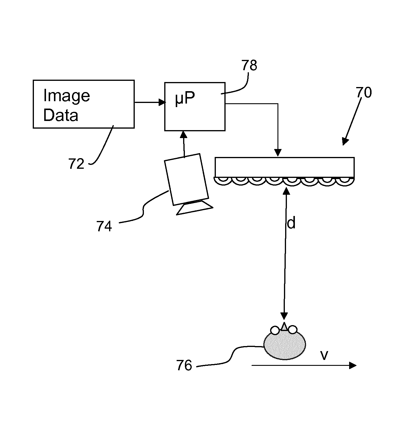
[0042]The invention provides an autostereoscopic display device in which a viewer tracking system determines a position of a viewer with respect to the display panel. The display panel is controlled to display a number of different views which is dependent on at least the distance of the viewer from the display panel. This enables the number of views to optimised with respect to the viewer position and optionally also the speed of movement of the viewer.

[0043]The known autostereoscopic display design will first be described.

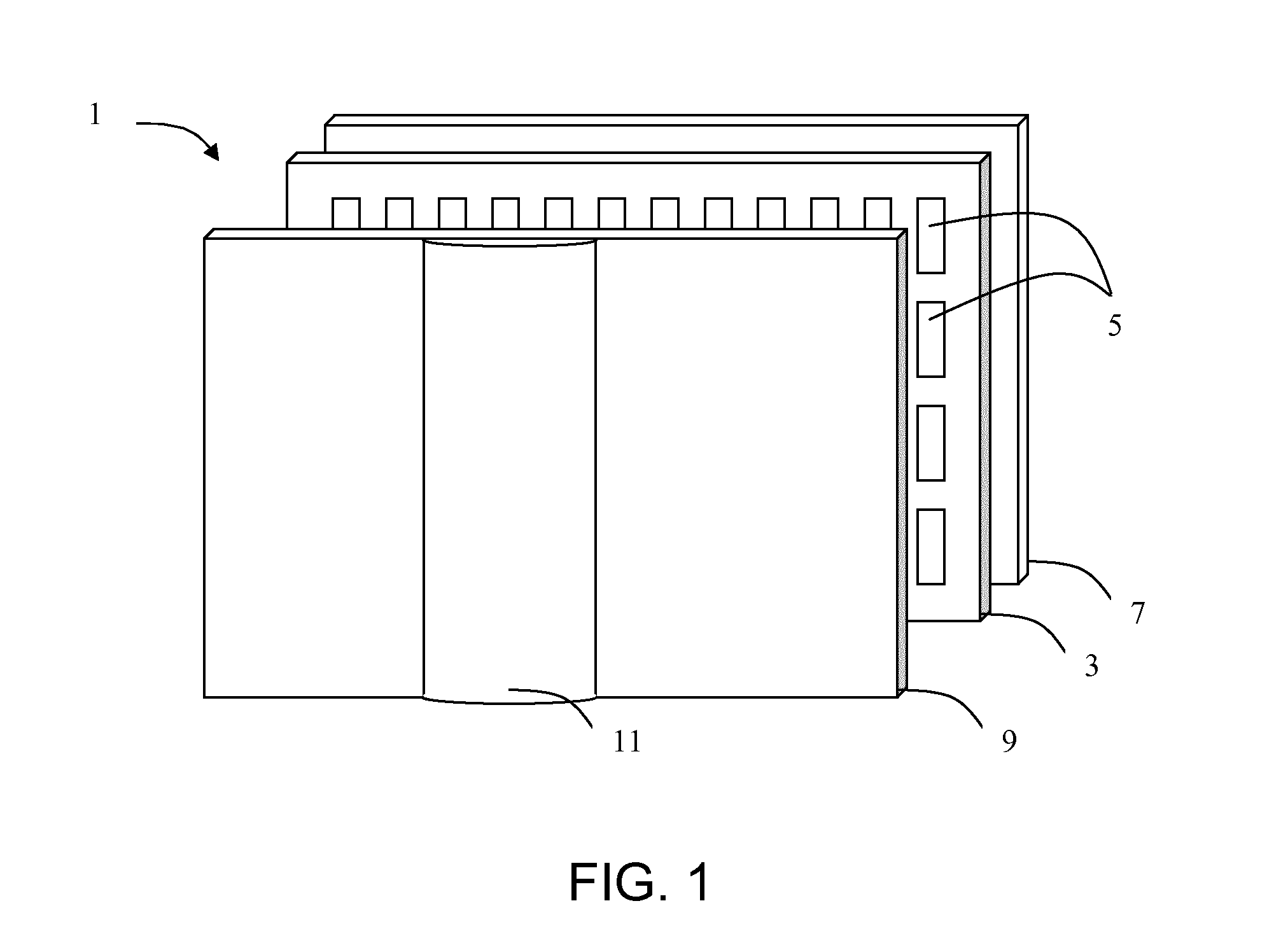
[0044]FIG. 1 is a schematic perspective view of a known direct view autostereoscopic display device 1. The known device 1 comprises a liquid crystal display panel 3 of the active matrix type that acts as a spatial light modulator to produce the display.

[0045]The display panel 3 has an orthogonal array of display pixels 5 arranged in rows and columns. For the sake of clarity, only a small number of display pixels 5 are shown in the Figure. In practice, the display...


PUM


Abstract

The invention provides an autostereoscopic display device in which a viewer tracking system determines a position of a viewer with respect to the display panel. The display panel is controlled to display a number of different views which is dependent on at least the distance of the viewer from the display panel. This enables the number of views to optimized with respect to the position and / or speed of movement of the viewer.

Description

FIELD OF THE INVENTION[0001]This invention relates to an autostereoscopic display device of the type that comprises a display panel having an array of display pixels for producing a display and an imaging arrangement for directing different views to different spatial positions.BACKGROUND OF THE INVENTION[0002]A first example of an imaging arrangement for use in this type of display is a barrier, for example with slits that are sized and positioned in relation to the underlying pixels of the display. In a two-view design, the viewer is able to perceive a 3D image if his / her head is at a fixed position. The barrier is positioned in front of the display panel and is designed so that light from the odd and even pixel columns is directed towards the left and right eye of the viewer, respectively.[0003]A drawback of this type of two-view display design is that the viewer has to be at a fixed position, and can only move approximately 3 cm to the left or right. In a more preferred embodimen...

Claims


Application Information

Patent Timeline
Patent Type & Authority Patents(United States)
IPC IPC(8): H04N13/04H04N13/00
CPCH04N13/0475H04N13/0014H04N13/0404H04N13/047H04N13/0447H04N13/0454H04N13/0477H04N13/0497H04N13/0409H04N13/117H04N13/305H04N13/31H04N13/351H04N13/359H04N13/368H04N13/373H04N13/376H04N13/398H04N13/302G02B27/0093G02B30/00H04N13/30
Inventor VAN DER HORST, JAN
Owner DIMENCO HLDG BV
Learn More