Micro jet gas film generation apparatus

a gas film and micro-jet technology, applied in mechanical equipment, machines/engines, sustainable transportation, etc., can solve the problems of difficult fabrication, complex tube design, and inability to continuously form gas film to protect metal surfaces, so as to reduce the amount of gas needed, improve cooling, and consume less gas

Active Publication Date: 2016-11-08
NAT CHUNG SHAN INST SCI & TECH
View PDF3 Cites 3 Cited by
  • Summary
  • Abstract
  • Description
  • Claims
  • Application Information

AI Technical Summary

Benefits of technology

[0009]By means of the structure set forth above, the micro jet gas film generated by the invention cannot produce a large eddy due to the lack of sufficient energy, hence can maintain a thin film a long distance after ejection to improve cooling and heat insulation effect. In addition, the spout is formed at a smaller diameter and consumes less gas, thus it also can reduce the amount of gas needed. As a result, the invention can provide many advantages over the conventional techniques, such as simpler design, and easier installation and implementation.

Problems solved by technology

As a result, a certain distance after ejection, the free jet is mixed with high temperature airflow, and gas film can no longer be formed continuously to protect the metal surface.
However, the embedded micro tube is complex in design and must be built inside the streamline body, it is quite difficult in fabrication.
Moreover, cooling is a problem not only happened to the turbine blades.
However, as the chip is shrunk constantly, the cooling method that adopts the radiation fins and air fan can no longer meet cooling requirement.

Method used


Image

  • Micro jet gas film generation apparatus
  • Micro jet gas film generation apparatus
  • Micro jet gas film generation apparatus

Examples


Embodiment Construction

Brief Description of the Drawings

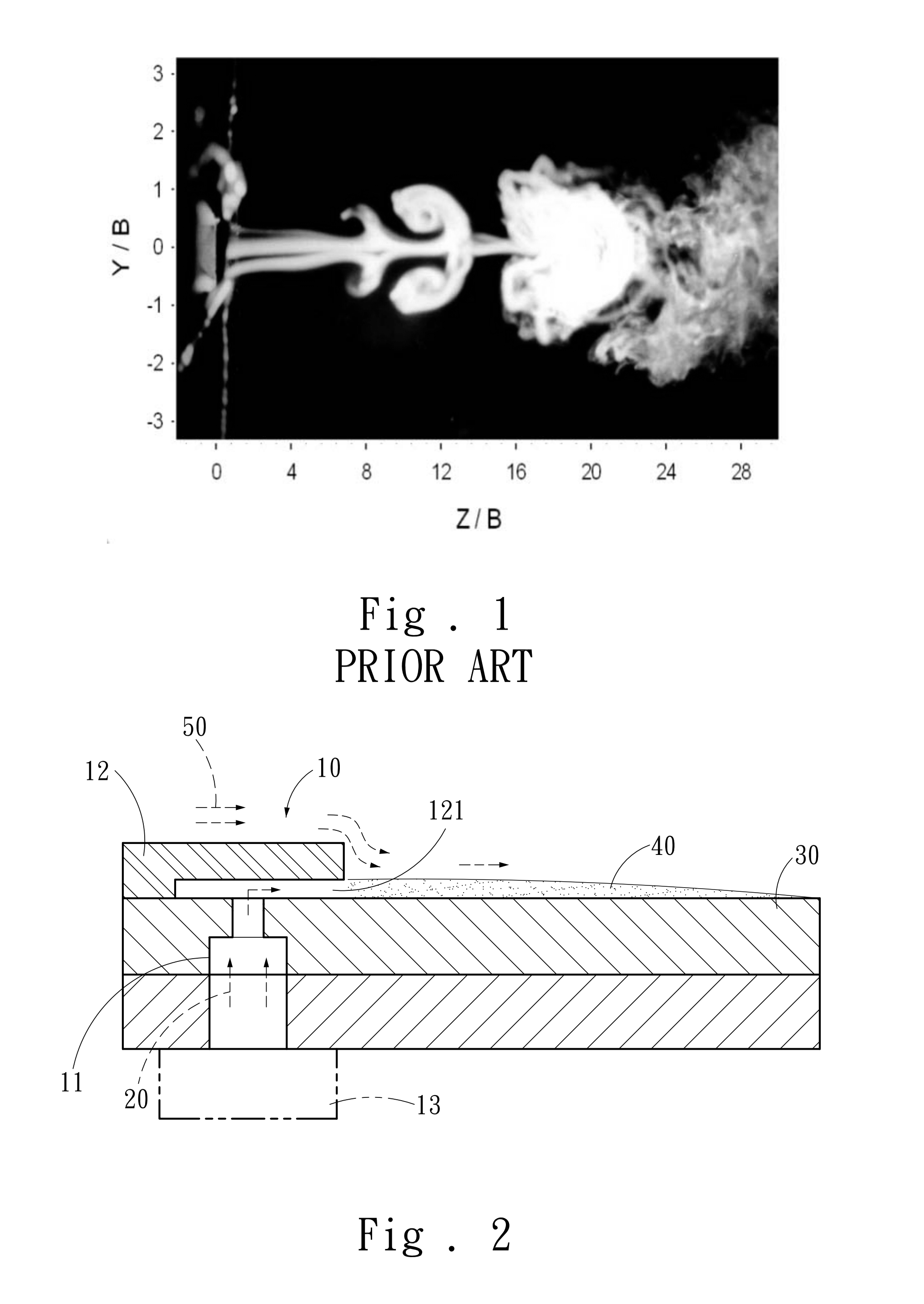
[0011]FIG. 1 is a schematic view of airflow ejection of conventional techniques.

[0012]FIG. 2 is a sectional view of an embodiment of the invention.

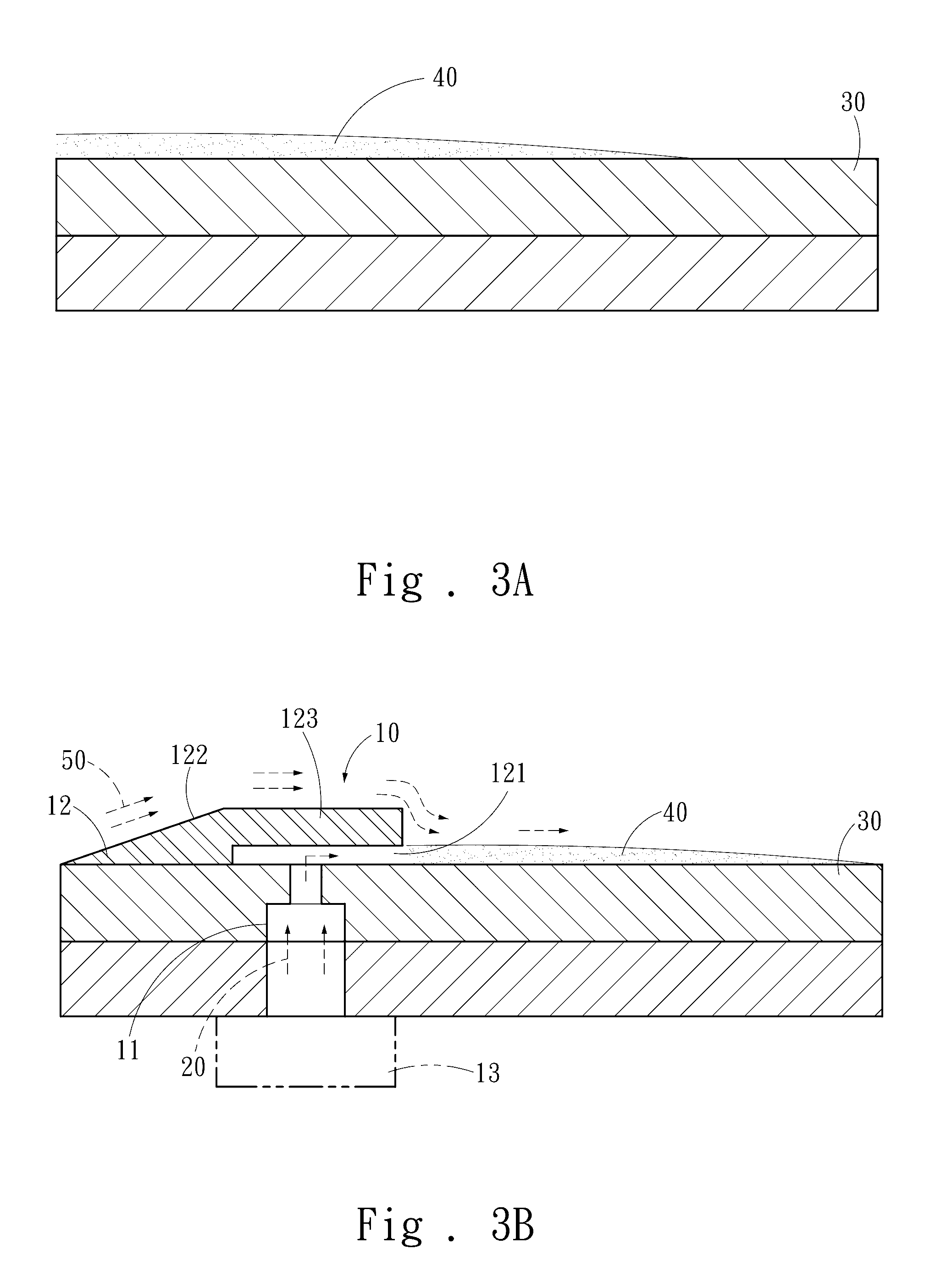
[0013]FIG. 3A is a schematic view of an embodiment of the invention in an ideal condition.

[0014]FIG. 3B is a schematic view of an embodiment of the invention in an actual use condition.

[0015]FIG. 3C is a fragmentary enlarged view of an embodiment of the invention.

[0016]FIG. 4 is a schematic view of an embodiment of the invention in a micro jet ejecting condition.

[0017]FIG. 5 is a chart showing cooling performance comparison between the invention and a conventional technique.

DETAILED DESCRIPTION OF THE PREFERRED EMBODIMENT

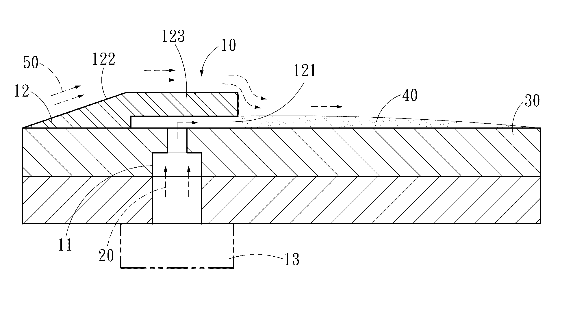
[0018]Please refer to FIG. 2, the present invention aims to provide a micro jet gas film generation apparatus 10 which is fabricated through micro-electromechanical technology. The micro jet gas film generation apparatus 10 is located on a work object 30 and includes at least one airflow p...


PUM


Abstract

A micro jet gas film generation apparatus aims to eject a gas to a work object which is desired for cooling or insulating from heat. The micro jet gas film generation apparatus has a spout formed at a diameter of 5-100 μm to generate a gas film on the work object. As the diameter of the spout of the micro jet gas film generation apparatus is small, the micro jet gas film generated from the spout cannot produce a large eddy due to the lack of sufficient energy, hence can maintain a thin film after a long distance ejection to improve cooling and heat insulation performance. Moreover, due to the small diameter of the spout, it also consumes less gas and can reduce the amount of gas required.

Description

FIELD OF THE INVENTION[0001]The present invention relates to a cooling and heat insulation structure and particularly to a micro jet gas film generation apparatus used for cooling and heat insulation.BACKGROUND OF THE INVENTION[0002]Modern high performance gas turbines have intake temperature proximate 2,000K. In order to protect the blades, forming a cooling gas film on the metal surface of the blades through cooling airflow generated by free jet is one of the most commonly used methods to reduce the thermal stress load of the gas turbine blades.[0003]According to liquid state stability theory, a jet has an unstable state with a symmetrical eddy, which is generated by mixing natural jet with external air. As the shearing stress generated by velocity causes turbulence to grow exponentially toward downstream, after the most unstable fluctuation has grown to a certain degree, a nonlinear effect is generated and an eddy with a regular arrangement and specific frequency by rolling up is...

Claims


Application Information

Patent Timeline
Patent Type & Authority Patents(United States)
IPC IPC(8): F01D5/18F02C7/18H05K7/20F01D25/14
CPCF01D5/186F02C7/18F01D25/14F05D2260/202F05D2260/204H05K7/20Y02T50/675Y02T50/60
Inventor JENG, DUN-ZENWANG, CHAO-CHINGCHIEN, TING-HUAKAO, CHI
Owner NAT CHUNG SHAN INST SCI & TECH
Why Eureka
Try Eureka