Eureka AIR delivers breakthrough ideas for toughest innovation challenges, trusted by R&D personnel around the world.

Transportable solar power system

a solar power system and self-contained technology, applied in the field of solar energy, to achieve the effect of maximizing the sun's exposure of the array

Active Publication Date: 2016-11-08
STRAHM MICHAEL
View PDF34 Cites 8 Cited by
  • Summary
  • Abstract
  • Description
  • Claims
  • Application Information

AI Technical Summary

Benefits of technology

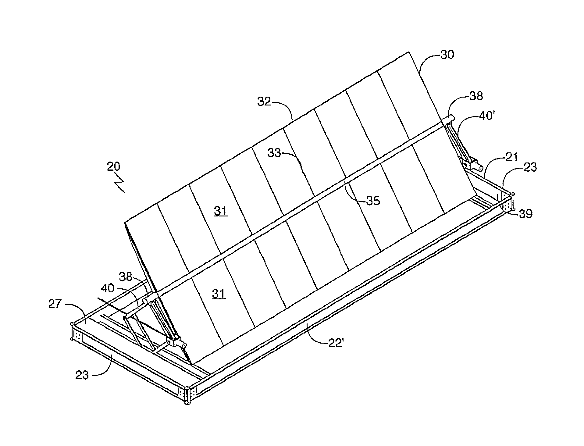
[0004]The present invention overcomes the limitations of prior art mobile power supplies by providing a transportable, self-contained, solar power system comprised of a plurality of individual solar power arrays, each array being contained within a transportable frame. Each array is folded into a frame during transportation. Upon reaching a desired location, the frame is positioned at a desired location, leveled and anchored. The frame then acts as a base while its solar power array is activated and deployed. If, during deployment, weather or environmental conditions become severe, the array may be folded back into its frame until conditions improve. The array has the capability of tracking the position of the sun during deployment. Each frame has a global positioning system (GPS) and a controller containing a chart of sun locations for a given location. The controller positions a frame's solar array to maximize the array's exposure to the sun. Each frame has a battery system, enabling a frame's solar array to self-start after a period of darkness.

Problems solved by technology

Where road transportation is difficult or impossible, or the distances involved are substantial, cargo containers may be transported by boat, airplane, helicopter, or the like, to the actual desired location or a nearby location for truck transport to the actual desired site.

Method used


Image

  • Transportable solar power system
  • Transportable solar power system
  • Transportable solar power system

Examples


Embodiment Construction

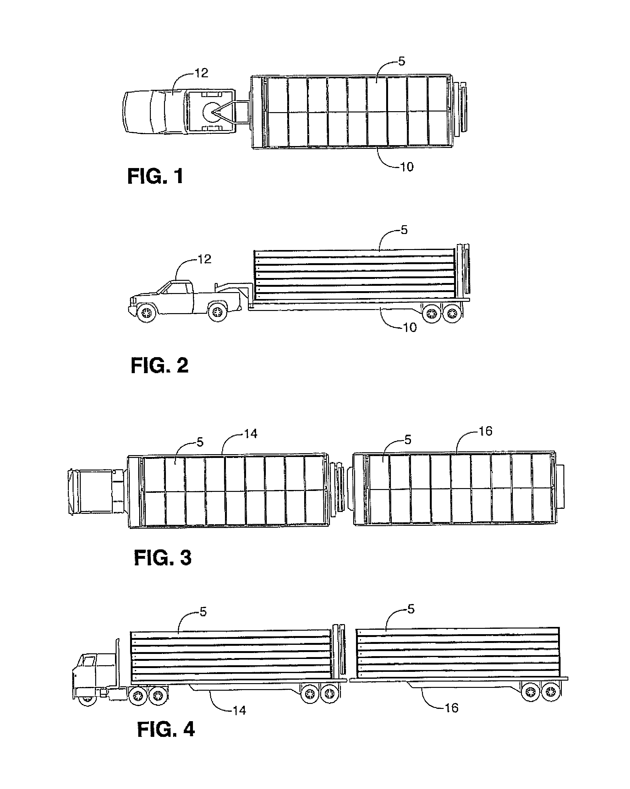
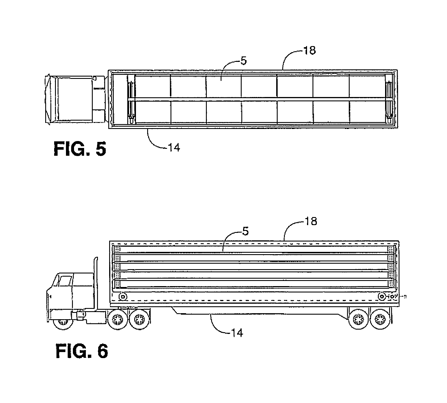
[0032]Referring to the drawings in detail wherein like elements are indicated by like numerals, there are illustrated in FIGS. 1 and 2, a trailer unit 10 hauled by a pickup truck 12. The trailer unit 10 contains a plurality of array frames 5. FIGS. 3 and 4 illustrate a tractor train comprised of a tractor trailer 14 and a towed trailer 16. The tractor trailer 14 and towed trailed 16 contain a plurality of array frames 5. FIGS. 5 and 6 illustrate a tractor trailer 14 supporting a cargo container 18 holding a plurality of array frames 5.

[0033]The array frames 5 are of two basic types, uni-tracker 20 and dual tracker 50. A uni-tracker array frame 20 is comprised of a frame 21 containing a solar panel array 30 joined to the frame 21 by means of a positioning apparatus 40 adapted to lift the solar panel array 30 above the frame and rotate the solar panel array 30 about a single longitudinal axis. A dual tracker array frame 50 is comprised of a frame 51 containing a solar panel array 70 j...


PUM


Abstract

A transportable, self-contained, solar power system comprised of a plurality of individual solar power arrays, each array being contained within a transportable frame. Each array is folded into a frame during transportation. Upon reaching a desired location, the frame is positioned at a desired location. The frame then acts as a base while its solar power array is activated and deployed. The array has the capability of tracking the position of the sun during deployment. Each frame has a global positioning system (GPS) and a controller containing a chart of sun locations for a given location. The controller positions a frame's solar array to maximize the array's exposure to the sun. Each frame has a battery system, enabling a frame's solar array to self-start after a period of darkness.

Description

CROSS-REFERENCE TO RELATED APPLICATIONS[0001]Division of application Ser. No. 12 / 586,570, filed on Sep. 24, 2009, now U.S. Pat. No. 8,492,645. Applicant claims the priority benefits of U.S. Provisional Patent Application No. 61 / 214,306, filed Apr. 22, 2009.BACKGROUND OF THE INVENTION[0002]This invention relates generally to the field of solar energy and, in particular, to a transportable, self-contained, solar power system.[0003]Mobile power supplies, operated with liquid fuels, are used in areas where conventional, electric power is unavailable or to supplement available electric power. Examples of this are areas where environmental and / or weather conditions have interrupted or destroyed conventional power grids. Other examples are undeveloped areas, remote areas, or sparsely populated areas without electric power or with limited available power, industrial applications, and military deployments. Prior art mobile power supplies are primarily limited by the fuel necessary for operat...

Claims


Application Information

Patent Timeline
Patent Type & Authority Patents(United States)
IPC IPC(8): H01L31/054H01L31/052H02S30/20F24S50/20
CPCH01L31/0522H01L31/045F24S30/455F24S50/20F24S2025/012H02S10/40H02S20/32H02S30/20H01L31/054Y02E10/47Y02E10/52
Inventor STRAHM, MICHAEL
Owner STRAHM MICHAEL
Why Eureka
Eureka Blog
Learn More