
Method for calibrating a multiphase inverter, operating apparatus, computer program, and computer program product

a multi-phase inverter and multi-phase technology, applied in the field of multi-phase inverters, can solve problems such as torque oscillations and errors in the calculated torques of electric machines, and achieve the effect of reducing amplifier errors

Active Publication Date: 2016-11-08
ROBERT BOSCH GMBH
View PDF5 Cites 0 Cited by
  • Summary
  • Abstract
  • Description
  • Claims
  • Application Information

AI Technical Summary

Benefits of technology

The invention provides a method for reducing amplification errors in current measurement and compensating for differences in amplification errors that can affect current regulation. The method involves switching off all switching elements in the inverter and measuring the currents in different phases. The measured currents are used to generate a mean value, which is used to calibrate the inverter. This calibration reduces amplification errors and ensures that the remaining amplification error is the same for all current sensors. The method is repeated until all possible mean values have been detected or all possible combinations of switching element switch-on operations have been implemented. This ensures that the differences in amplification errors are overall compensated for. The method can be implemented without generating any torque, which prevents any negative effects on the surrounding environment, such as drive torque on driving wheels of a motor vehicle.

Problems solved by technology

Errors in the measured currents result firstly in errors in the calculated torques of the electric machine and secondly also in torque oscillations which have a negative effect on a drive response of the electric machine.

Method used


Image

  • Method for calibrating a multiphase inverter, operating apparatus, computer program, and computer program product
  • Method for calibrating a multiphase inverter, operating apparatus, computer program, and computer program product
  • Method for calibrating a multiphase inverter, operating apparatus, computer program, and computer program product

Examples


Embodiment Construction

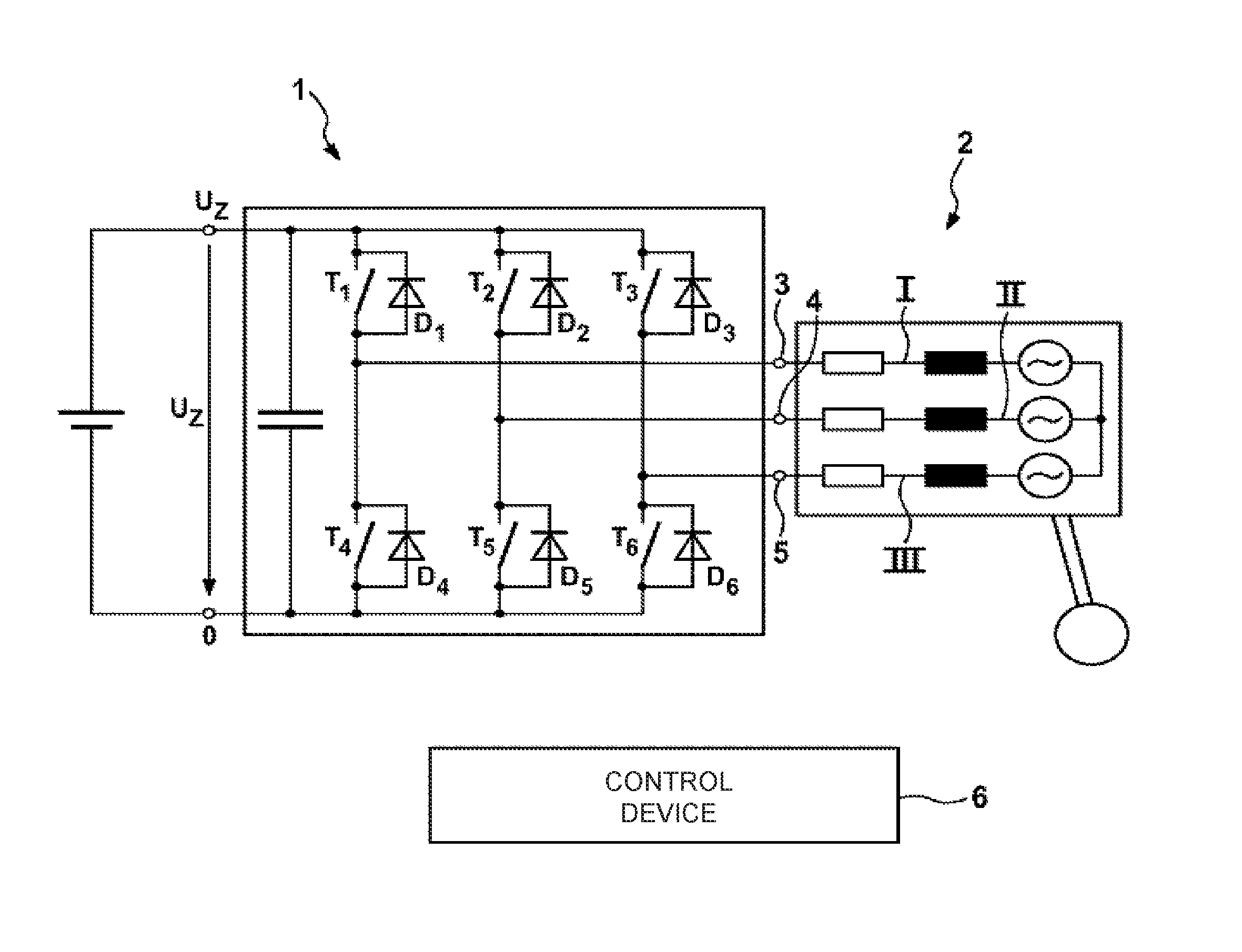
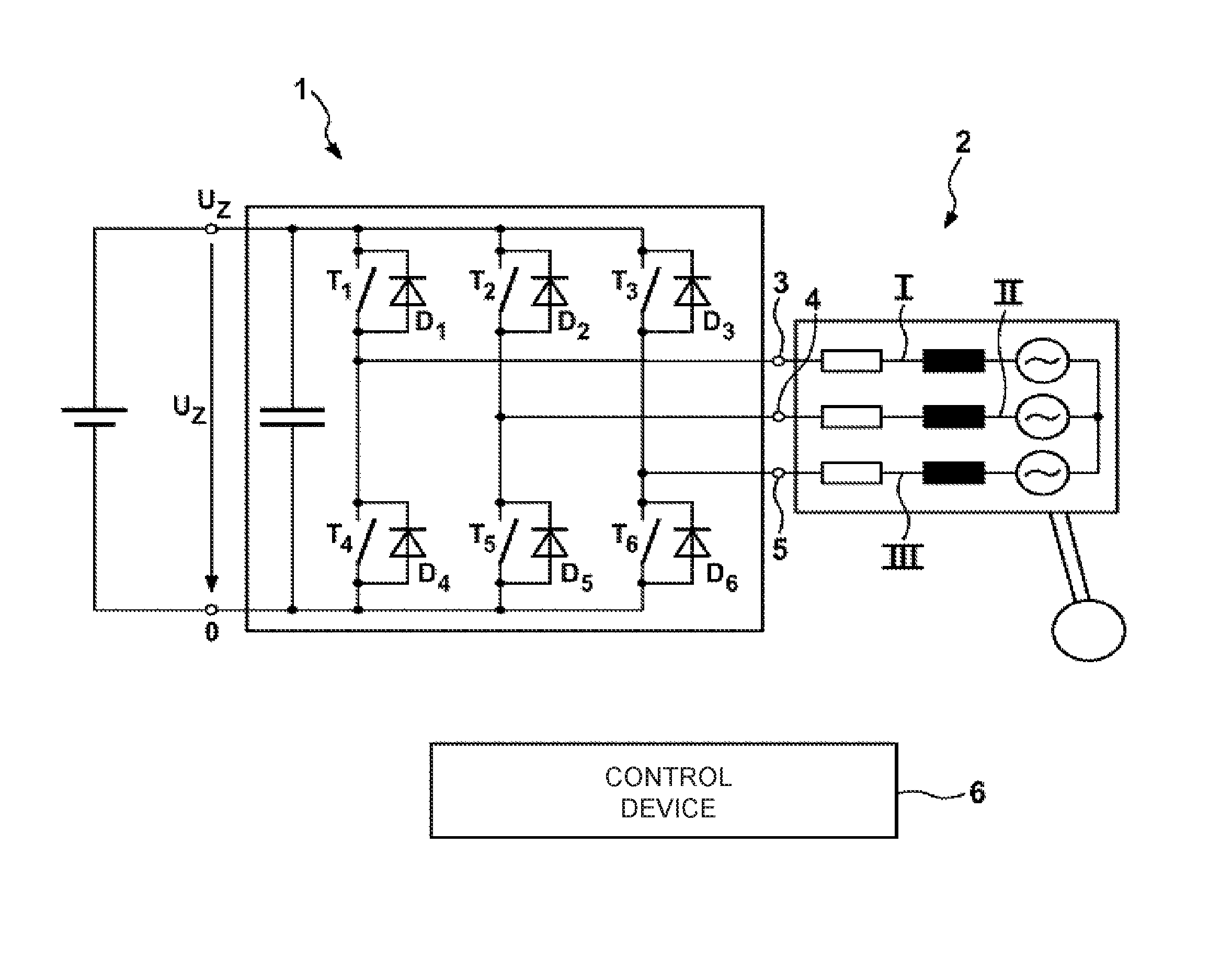
[0015]The FIGURE shows, in a schematic illustration, an inverter 1, which is connected to a polyphase machine 2 for the operation thereof. The polyphase machine 2, which is in the form of an asynchronous machine, for example, has three winding phases or phases I, II and III. The phases I, II and III are star-connected to one another, for example. The inverter 1 has a bridge circuit for actuating the phases I, II and III. Said bridge circuit has a switching element T1 on the high-voltage side and a switching element T4 on the low-voltage side for phase I. In this case, a freewheeling diode D1 is assigned to the switching element T1 on the high-voltage side and a freewheeling diode D4 is assigned to the switching element T1, in each case in parallel. Furthermore the bridge circuit has a switching element T2 on the high-voltage side and a switching element T5 on the low-voltage side for phase II. In this case, a freewheeling diode D2 is assigned to the switching element T2 and a freewh...


PUM


Abstract

The invention relates to a method for calibrating a multiphase, in particular three-phase, inverter (1) having a respective switching element (T1, T2, T3) on the high-voltage side and a respective switching element (T4, T5, T6) on the low-voltage side for each of the phases thereof as well as a respective current sensor for at least some of the phases (I, II, III). The following steps are proposed: (f) switching off all switching elements (T1-T6), (g) switching on a switching element (T1) on the high-voltage side for a first phase (I) and a switching element (T5) on the low-voltage side for a second phase (II), (h) measuring the currents flowing through the first phase (I) and the second phase (II), (i) forming an average value from the measured currents, and (j) calibrating the inverter (1) on the basis of the formed average value. The invention also relates to an apparatus, a computer program and a computer program product.

Description

BACKGROUND OF THE INVENTION[0001]The invention relates to a method for calibrating a multiphase, in particular three-phase inverter, in particular a pulse-controlled inverter, which has, for each of its phases, in each case one switching element on the high-voltage side and in each case one switching element on the low-voltage side and, for at least two of the phases, in each case one current sensor.[0002]In addition, the invention relates to an apparatus for operating such an inverter, and to a computer program and to a computer program product.[0003]For actuating electric machines, in particular for actuating polyphase machines, inverters are provided which supply current to three in particular star-connected or delta-connected phases of the electric machine. Generally, such inverters have, for each of the phases, a switching element on the high-voltage side and a switching element on the low-voltage side, which switching elements are switchable independently of one another and fo...

Claims


Application Information

Patent Timeline
Patent Type & Authority Patents(United States)
IPC IPC(8): H02P27/06H02M7/5387H02M1/00
CPCH02M7/53871H02P27/06H02M2001/0009H02M1/0009
Inventor RAICHLE, DANIELDAMSON, MARK
Owner ROBERT BOSCH GMBH
Learn More