Cylindrical housing with locking ring

a technology of locking ring and cylindrical housing, which is applied in the direction of cable junctions, optical elements, instruments, etc., can solve the problems of thick walled housings and the inability of welding methods to re-enter the pressure vessel, and achieve the effect of increasing the usable volume inside the pressure vessel and reducing the number of components

Inactive Publication Date: 2016-11-15
AFL COMM LLC
View PDF4 Cites 2 Cited by
  • Summary
  • Abstract
  • Description
  • Claims
  • Application Information

AI Technical Summary

Benefits of technology

[0016]One embodiment of the present invention utilizes a single self-supporting slide shell, not requiring a separate internal support structure, while still supporting an application pressure of many thousands of pounds per square inch. When the pressure housing shell itself provides the internal support, the number of components are reduced and the usable volume inside the pressure vessel increases.
[0017]Other features of the embodiment may include a simplified threaded closure ring that secures the self-supporting slide shell in place without the requirement of multiple fasteners and protracted assembly times.

Problems solved by technology

One of the key challenges in subsea system design is to provide a one atmosphere hollow pressure vessel attached to transmission cables that can be used to house components needed in various subsea industries such as communications, defense and offshore oil and gas markets with the ability to withstand the hydrostatic pressures of deep and ultra-deep sea environments.
Designing this type of pressure vessel to be hermetically sealed and resistant to corrosion while making the pressure housing capable of being re-entered if necessary has proven to be a significant design challenge.
One significant challenge has been to maintain the structural integrity of the pressure vessel housing while keeping the overall weight as light as possible for assembly and deployment purposes.
This welded method does not allow re-entry into the pressure vessel if needed during the manufacturing, testing and handling prior to deployment.
The bolted case and cover method requires a significant number of high strength fasteners and extra material around the fasteners to transfer the load into the housing components resulting in thick walled housings.

Method used


Image

  • Cylindrical housing with locking ring
  • Cylindrical housing with locking ring
  • Cylindrical housing with locking ring

Examples


Embodiment Construction

[0033]The following detailed description is provided to assist the reader in gaining a comprehensive understanding of the methods, apparatuses and / or systems described herein. Various changes, modifications, and equivalents of the systems, apparatuses and / or methods described herein will suggest themselves to those of ordinary skill in the art. Descriptions of well-known functions and structures are omitted to enhance clarity and conciseness.

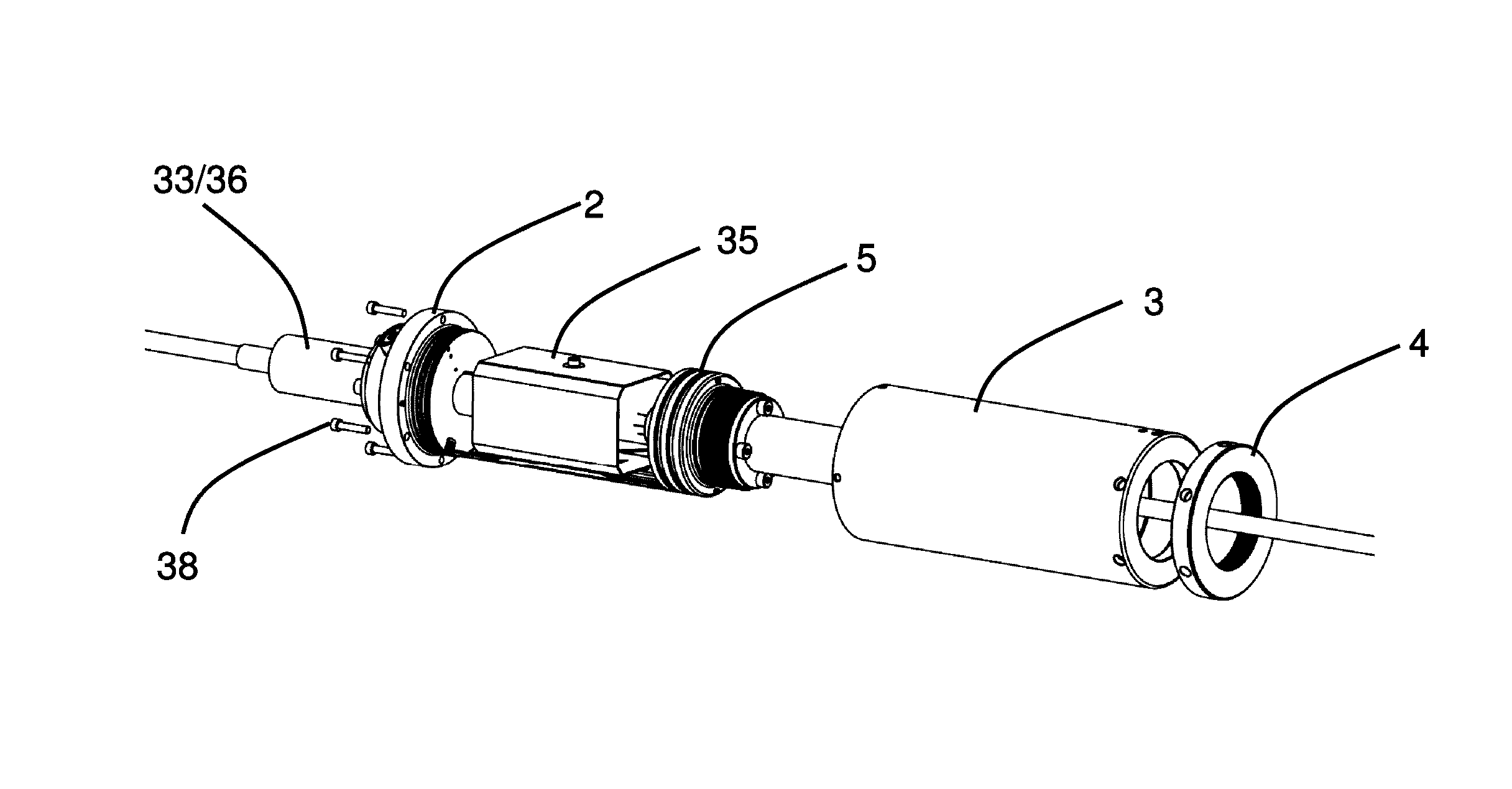
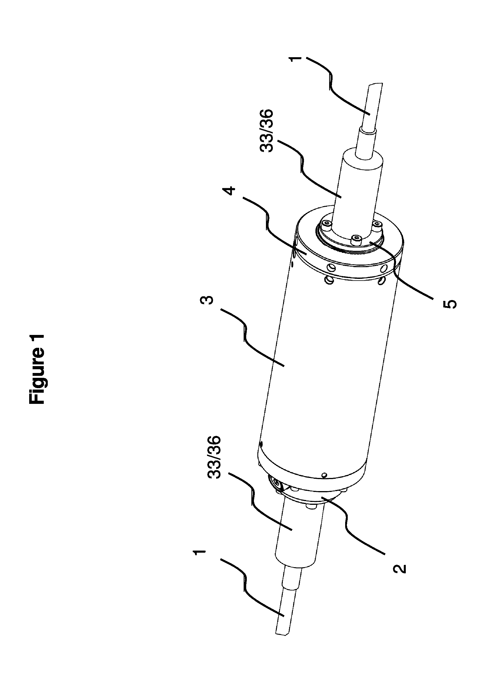
[0034]FIG. 1 shows an isometric view of an exemplary embodiment of an assembled slide cylinder pressure vessel. Some of the major components are identified and the pressure vessel in this instance is shown connected to a cable 1 on each end. The vessel includes a slide cylinder pressure housing 3, a first end cap 2, a second end cap 5, an end cap locking ring 4 and terminations 33, such as an armored termination, epoxy gland, penetrator, etc. In this embodiment, the terminations 33 are underneath a pre-overmolded polyurethane boot 36. Details of...


PUM


Abstract

A pressure apparatus including a first end cap, a second end cap, a hollow housing connected to the first and second end caps, a locking ring connected to the second end cap, a first termination connected to the first end cap, and a second termination connected to the second end cap.

Description

CROSS-REFERENCE TO RELATED APPLICATIONS[0001]This application is based upon and claims the benefit of priority from U.S. Provisional Application No. 61 / 613,106, filed Mar. 20, 2012, in the United States Patent and Trademark Office, the disclosures of which are incorporated herein in its entirety by reference.BACKGROUND[0002]1. Field[0003]The invention is related to a pressure housing assembly, and more particularly to pressure housing assembly suitable for use in underwater environments.[0004]2. Related Art[0005]One of the key challenges in subsea system design is to provide a one atmosphere hollow pressure vessel attached to transmission cables that can be used to house components needed in various subsea industries such as communications, defense and offshore oil and gas markets with the ability to withstand the hydrostatic pressures of deep and ultra-deep sea environments. Designing this type of pressure vessel to be hermetically sealed and resistant to corrosion while making the...

Claims


Application Information

Patent Timeline
Patent Type & Authority Patents(United States)
IPC IPC(8): G02B6/44H02G15/115H02G15/14
CPCG02B6/4427H02G15/115G02B6/4428G02B6/4454H02G15/14
Inventor KIMBRELL, EDDIELICHOULAS, TEDTOTH, JOHN
Owner AFL COMM LLC
Why Eureka
Try Eureka