Method and apparatus for polar receiver with digital demodulation

a technology of polar receiver and digital demodulation, applied in the field of method and apparatus for polar receiver with digital demodulation, can solve the problems of poor performance and high bit error rate (ber)

Active Publication Date: 2016-11-15
INNOPHASE
View PDF39 Cites 19 Cited by
  • Summary
  • Abstract
  • Description
  • Claims
  • Application Information

AI Technical Summary

Problems solved by technology

However, the proposed polar receiver architectures and associated signal processing have deficiencies that result in poor performance and high bit error rates (BER).

Method used


Image

  • Method and apparatus for polar receiver with digital demodulation
  • Method and apparatus for polar receiver with digital demodulation
  • Method and apparatus for polar receiver with digital demodulation

Examples


Embodiment Construction

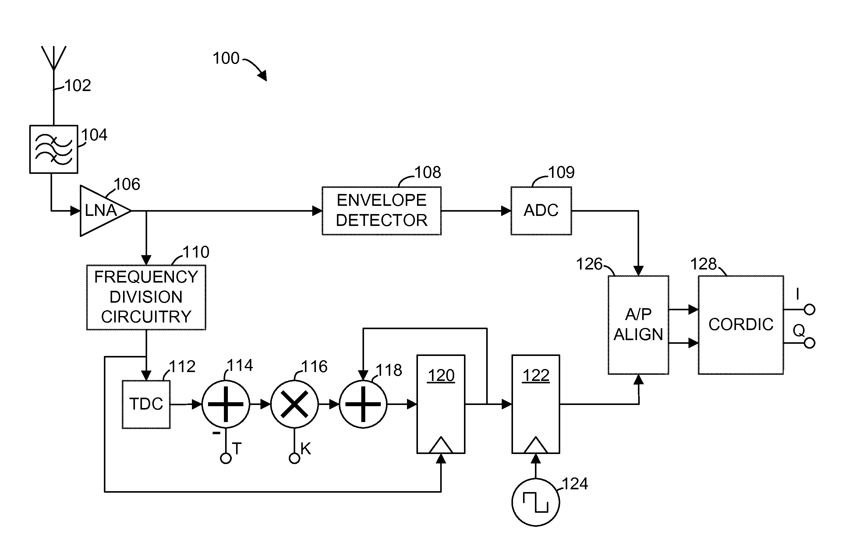
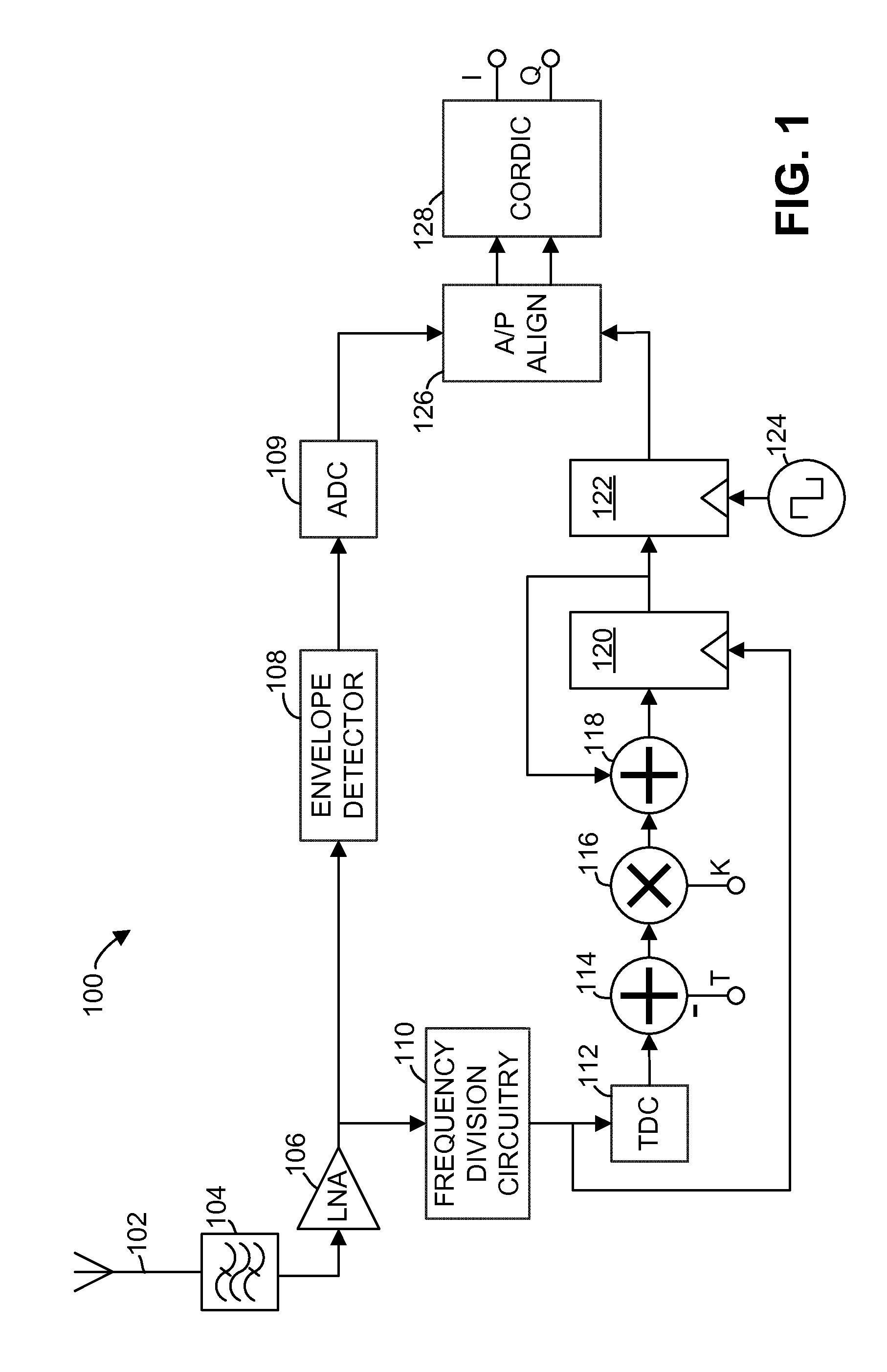
[0011]In an exemplary embodiment illustrated in FIG. 1, a polar receiver 100 receives an incoming radio-frequency (RF) signal through an input node, such as antenna 102. In some embodiments, the incoming radio-frequency signal, also referred to herein as a modulated carrier signal, has a frequency in the range of 2412 MHz-2484 MHz, although the use of the polar receiver 100 is not limited to that frequency range. The incoming radio-frequency signal is filtered by a bandpass filter 104 and amplified by a low-noise amplifier (LNA) 106. The polar receiver 100 operates to receive and decode frequency modulated or phase-modulated radio-frequency signals, such as signals modulated using phase shift keying (PSK) or quadrature amplitude modulation (QAM). As the term is used in the present disclosure, phase-modulated signals include signals that are modulated in phase (e.g., binary phase-shift keying, quadrature phase-shift keying, 8-PSK, or 16-PSK) as well as signals that are modulated in b...


PUM


Abstract

Circuitry and methods are described for digital signal demodulation. In a polar receiver, a modulated radio-frequency input signal is provided to frequency division circuitry, which may include a harmonic injection-locked oscillator (ILO). The phase of the frequency-divided output is measured using a self-triggered time-to-digital converter (TDC), which may be a Vernier TDC. A subtractor subtracts a period offset from the output of the TDC to generate an offset digital time output, and a digital integrator integrates the offset digital time output. The integrated time signal represents the phase of the radio-frequency input signal and can be used to determine a symbol, such as a phase-shift keying (PSK) or quadrature amplitude modulation (QAM) symbol, conveyed by the modulated radio-frequency input signal.

Description

BACKGROUND[0001]Communications transceivers may utilize numerous architectures to recover data from a modulated carrier signal. These architectures include coherent demodulation, using either intermediate frequency conversion or direct-conversion receivers. Such receivers typically recover or regenerate the communications carrier signal using a phase-locked loop (PLL) and coherent demodulation. Recently, polar receiver architectures have been proposed that extract the modulation phase components from a received modulation signal without using a carrier recovery circuitry. However, the proposed polar receiver architectures and associated signal processing have deficiencies that result in poor performance and high bit error rates (BER). Accordingly, there is a need for improved polar receiver signal processing and architectures.BRIEF DESCRIPTION OF THE DRAWINGS[0002]The accompanying figures, where like reference numerals refer to identical or functionally similar elements throughout t...

Claims


Application Information

Patent Timeline
Patent Type & Authority Patents(United States)
IPC IPC(8): H04L27/00H04L27/22G06F3/033H04B1/06G01S13/70
CPCH04L27/22G01S13/70H04B1/06H04B1/18
Inventor XU, YANGHERMOSO, SARA MUNOZPEREZ, ROC BERENGUER
Owner INNOPHASE
Why Eureka
Try Eureka