
Apparatus and method for preventing tubing casing annulus pressure communication

a tubing casing and annulus technology, applied in the direction of fluid removal, sealing/packing, borehole/well accessories, etc., can solve the problems of tca communication, affecting both the sealing and the interior surface of the smooth bore, and damage to the seal stack inside the pbr, so as to reduce workover costs, mitigate tca communication, and minimize fluid exposure

Active Publication Date: 2016-11-22
SAUDI ARABIAN OIL CO
View PDF24 Cites 4 Cited by
  • Summary
  • Abstract
  • Description
  • Claims
  • Application Information

AI Technical Summary

Benefits of technology

The apparatus effectively mitigates TCA communication, reducing workover costs and ensuring reliable hydrocarbon production by providing a strong, self-healing seal that is tolerant to debris and temperature changes, thus enhancing operational safety and production reliability.

Problems solved by technology

TCA communication is a common problem in the gas production industry.
The main cause is damage to the seal stack inside the PBR due to movement of the seal stack (installation, “stabbing”, stimulation treatments) in the presence of debris around the seals.
Debris lodged between the seals and the PBR can cause damage to both the seals and the smooth bore interior surface (gouging) when the seals.
Chemical or thermal degradation of the seal stack seals may have occurred.
Wellbore and formation treatments can expose the seals to severe chemicals or increased fluid temperatures that cause the seals to degrade, albeit over time, such as through reaction of a minor components within the seal or through leeching of plasticizer that maintains pliability.
The seals are not designed to change shape, form or volume (shrink or swell), and so anything that could cause them to retract or expand, especially repeatedly, can cause the formation of cracks in the seal that eventually leads to a rupture.
The relative inflexibility of the design is a strength for forming the frictional seal, but it also results in the seal not being able to be repaired in place once the any defect is manifested, especially if the fluid is abrasive (gas or solids) in nature: the flow through the defect will degrade the polymer / rubber matrix material quickly.
This is a time consuming and therefore costly solution.
In addition, the prolonged shutdowns of a gas well (referred to “locked in potential”) may create additional costs in deferred profits or even force majeure in severe cases due to deferred production.
It is also not a perfect solution: the equipment associated with the old liner hanger packer and PBR may interfere with production potential by providing a downhole restriction.

Method used


Image

  • Apparatus and method for preventing tubing casing annulus pressure communication
  • Apparatus and method for preventing tubing casing annulus pressure communication
  • Apparatus and method for preventing tubing casing annulus pressure communication

Examples


Embodiment Construction

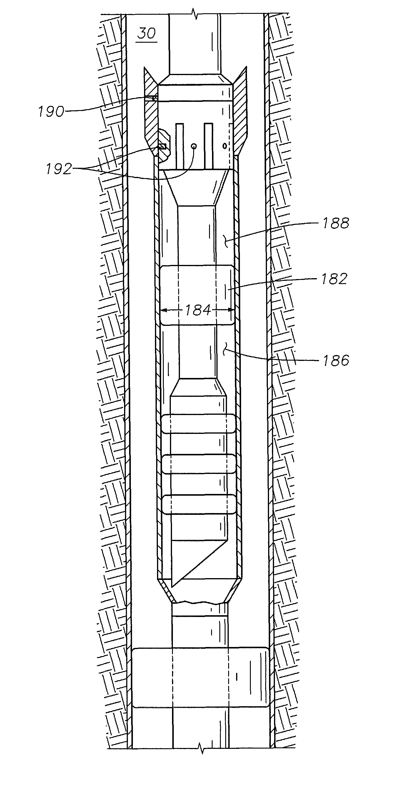
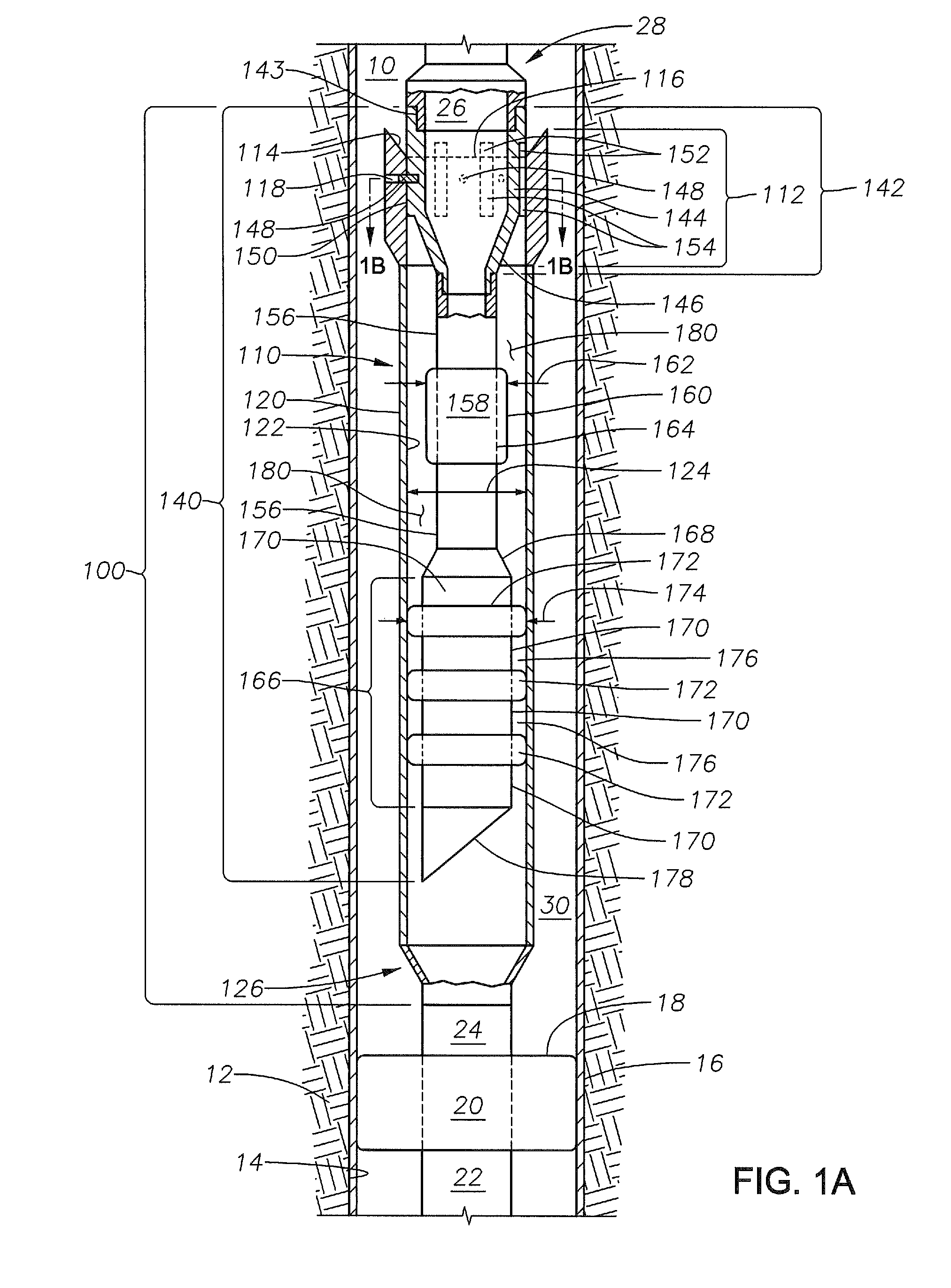
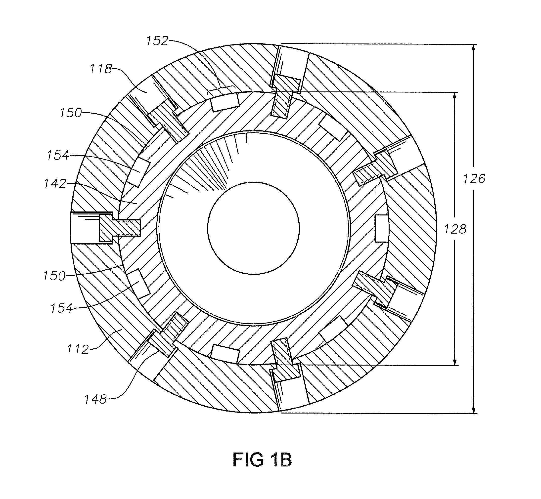
[0028]The Specification, which includes the Summary of Invention, Brief Description of the Drawings and the Detailed Description of the Preferred Embodiments, and the appended Claims refer to particular features (including process or method steps) of the invention. Those of skill in the art understand that the invention includes all possible combinations and uses of particular features described in the Specification. Those of skill in the art understand that the invention is not limited to or by the description of embodiments given in the Specification. The inventive subject matter is not restricted except only in the spirit of the Specification and appended Claims.

[0029]Those of skill in the art also understand that the terminology used for describing particular embodiments does not limit the scope or breadth of the invention. In interpreting the Specification and appended Claims, all terms should be interpreted in the broadest possible manner consistent with the context of each te...


PUM


Abstract

A method of installation of a completion assembly apparatus into a wellbore with a liner hangar packer includes introducing the completion assembly apparatus into the wellbore, where the hybrid sealing assembly couples to the polished bore receiver assembly such that the hybrid sealing assembly is not operable to move laterally within the polished bore receiver assembly, positioning the completion assembly apparatus such that the completion assembly apparatus couples with the liner hangar packer, which establishes fluid communication between the polished bore receiver assembly and a portion of the wellbore downhole from the liner hanger packer, and operating the completion assembly apparatus such that the hybrid sealing assembly decouples from the polished bore receiver assembly such that the hybrid sealing assembly is operable to move laterally within the polished bore receiver assembly. The hybrid sealing assembly includes an unswollen swellable packer operable to swell upon exposure to a swelling material.

Description

BACKGROUND OF THE INVENTION[0001]1. Field of the Invention[0002]The field of invention relates to downhole completions equipment and method of use. More specifically, the field relates to the prevention of tubing casing annulus (TCA) communication.[0003]2. Description of the Related Art[0004]After a wellbore is drilled to the required depth to access a hydrocarbon-bearing formation, a well completion assembly is introduced into and installed proximate to the hydrocarbon-bearing formation to allow controlled hydrocarbon production to the surface using production tubing. The completion assembly restricts produced fluid from traveling up the wellbore by funneling the produced fluid into production tubing that runs to the surface.[0005]The completion assembly is constructed in the wellbore after installing a liner hanger packer. The liner hanger packer has slips that engage the casing and elastic elements that provide a pressure seal against the casing. A completion assembly is usually ...

Claims


Application Information

Patent Timeline
Patent Type & Authority Patents(United States)
IPC IPC(8): E21B23/06E21B43/10E21B33/12E21B33/10E21B33/128
CPCE21B23/06E21B33/10E21B33/1208E21B33/1285E21B43/10
Inventor AL-RABEH, MAJED N.
Owner SAUDI ARABIAN OIL CO
Learn More