Variable orifice type pressure-controlled flow controller

a flow controller and variable orifice technology, applied in the direction of engine diaphragms, diaphragm valves, instruments, etc., can solve the problems of reducing manufacturing costs and product management, shortening the time to be taken to switch the flow control range, and many problems, so as to achieve accurate adjustment and shorten the lowering time

Active Publication Date: 2016-11-29
FUJIKIN INC
View PDF42 Cites 12 Cited by
  • Summary
  • Abstract
  • Description
  • Claims
  • Application Information

AI Technical Summary

Benefits of technology

[0031]The present invention is constituted so that a variable orifice drive unit 8 includes the eccentric cam 8a and the stepping motor 8b, and by turning the stepping motor 8b by 360 degrees or less, the cam plate 8a4 of the eccentric cam 8a is displaced in the left-right direction by a predetermined amount, and without rotating the cam plate 8a4, the diaphragm presser 7b of the variable orifice 7 is pressed and moved in the left-right direction by the cam plate 8a4 to adjust the clearance between the valve seat 10d5 of the variable orifice 7 and the diaphragm 7a (that is, the orifice hole diameter).
[0032]As a result, the orifice hole diameter can be extremely swiftly (that is, in approximately 0.1 to 0.5 seconds) and accurately adjusted by the eccentric cam 8a, and the flow rate range of the control flow rate of the flow controller can be extremely swiftly switched.
[0033]In the present invention, the flow rate arithmetic and control unit 4a of the pressure control unit 1a and the orifice opening degree arithmetic and control unit 4b of the variable orifice unit 1b form the control unit 4, and when the input value of the flow rate setting signal Qs into the flow rate arithmetic and control unit 4a changes at the time of switching of the control flow rate range, due to the change in the flow rate setting signal Qs, the orifice opening degree setting signal Qz to be input into the orifice opening degree arithmetic and control unit 4b is increased to 1.5 times or more to increase the opening degree of the variable orifice 7 to 1.5 times or more larger than the opening degree in the set flow rate range, and after a predetermined time elapses, the orifice opening degree control signal Qz is adjusted to a set value of the opening degree suitable for the flow rate range after switching of the control flow rate range, whereby performing flow control.
[0034]As a result, at the time of switching of the control flow rate, the fluid inside the upstream side fluid passage of the variable orifice 7 is smoothly and swiftly discharged to the downstream side through the orifice hole diameter smoothly and swiftly opened, and even if the valve seat hole diameter of the variable orifice 7 is 0.1 mm and has a small flow rate region the 100% set flow rate of which is 10 sccm, this can be lowered to the 20% set flow rate (2 sccm) in 1 second, so that the lowering time can be significantly shortened.

Problems solved by technology

However, when fixed orifices are used, orifices with different orifice hole diameters have to be prepared corresponding to the maximum control flow rates, and therefore, many kinds of pressure-controlled flow controllers with different flow rate ranges are inevitably prepared, and this poses various problems in reducing manufacturing costs and product management, etc.
However, many problems that should be solved still remain in the variable orifice type pressure-controlled flow controller shown in FIG. 12 and FIG. 13.
Among the problems, in recent years, shortening of the time to be taken to switch the flow control range has particularly become an issue, and shortening of the time required to switch the setting of the variable orifice 25 itself and significant shortening of the lowering time during use of the set variable orifice have been demanded.
However, the orifice drive unit 26 is mainly composed of the ball screw mechanism 39, so that a considerable amount of time (approximately 1 to 3 seconds) is required to adjust the clearance of the variable orifice 25 (orifice opening area setting), and switching of the flow control range cannot be swiftly performed.

Method used


Image

  • Variable orifice type pressure-controlled flow controller
  • Variable orifice type pressure-controlled flow controller
  • Variable orifice type pressure-controlled flow controller

Examples


Embodiment Construction

[0049]Hereinafter, preferred embodiments of the present invention are described with reference to the drawings, in which like parts are indicated by like reference numerals.

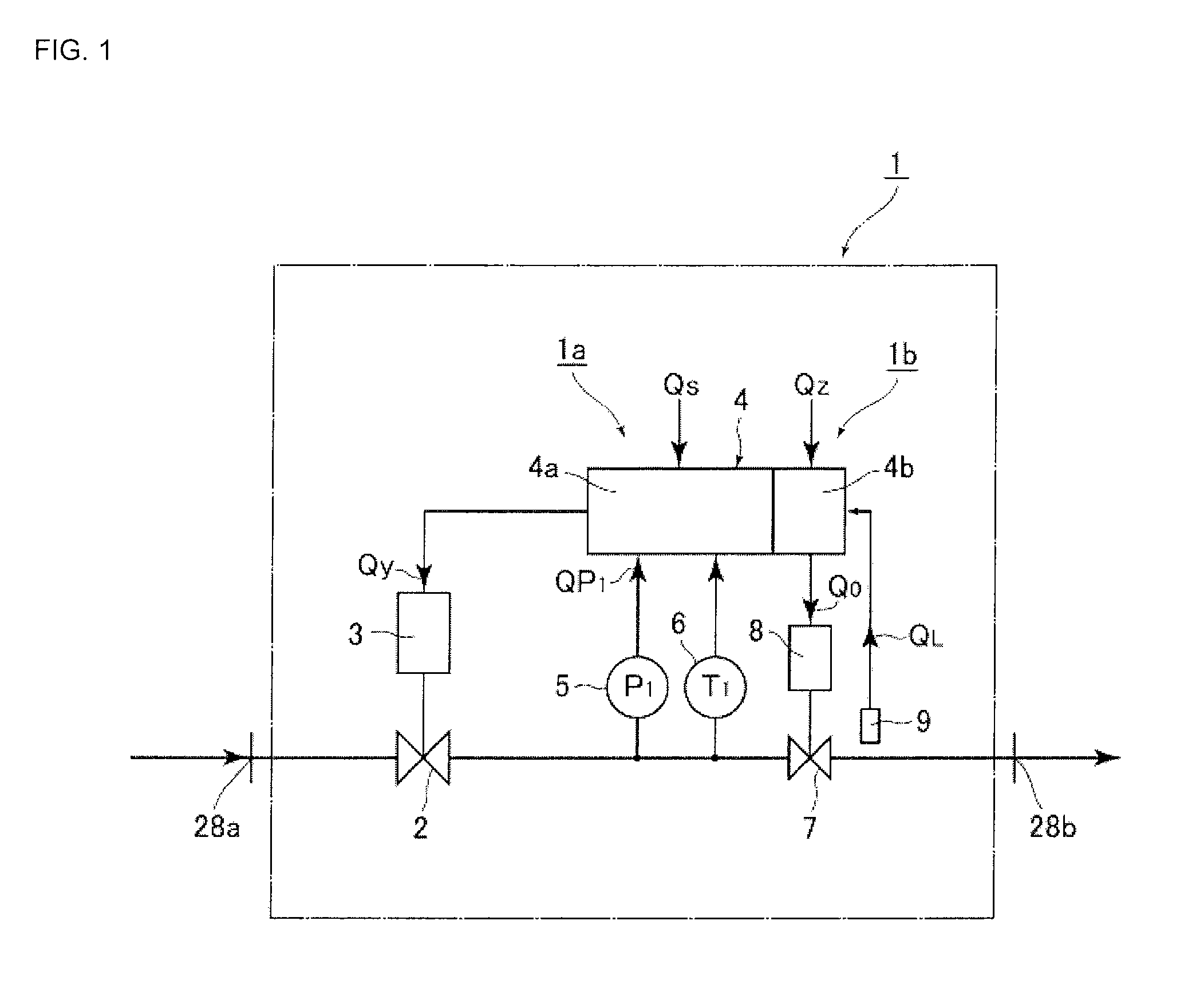
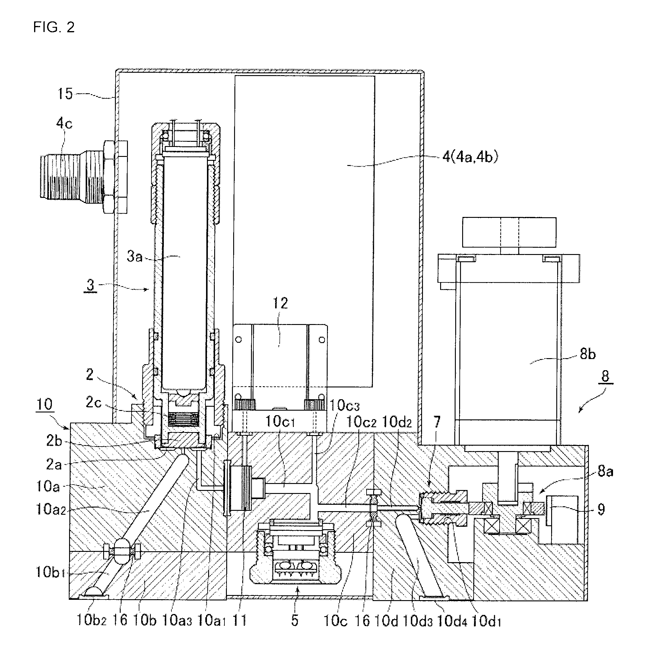
[0050]FIG. 1 is a systematic diagram showing a first preferred embodiment of the present invention. A pressure-controlled flow controller 1 according to the present invention includes a pressure control unit 1a and a variable orifice unit 1b. The pressure control unit 1a is analogous to the pressure control unit A of the conventional pressure-controlled flow controller 27 shown in FIG. 12, and is formed by a pressure control valve 2, a pressure control valve drive unit 3, a flow rate arithmetic and control unit 4a, a pressure detector 5, and a temperature detector 6, etc.

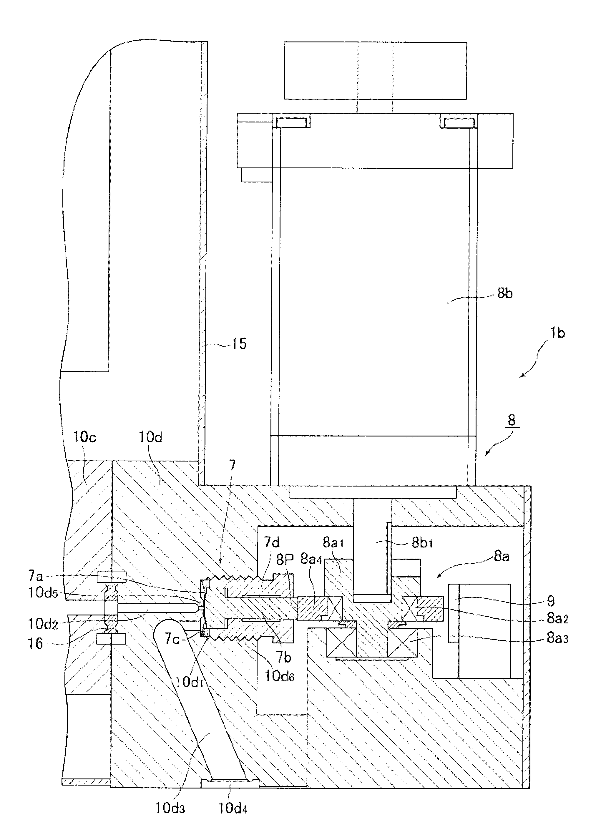
[0051]On the other hand, the variable orifice unit 1b uses a variable orifice (direct touch type metal diaphragm valve) 7 analogous to the conventional pressure control unit A shown in FIG. 12, however, the structures of the orifice drive unit 8 ...


PUM


Abstract

In a variable orifice type pressure-controlled flow controller that includes a pressure control unit and a variable orifice unit, computes a flow rate of a fluid distributed through an orifice of the variable orifice unit as QP1=KP1 (P1 is an orifice upstream side pressure and K is a constant), and switches a flow control range and performs flow control in the flow control range by changing a set flow rate signal Qs for a flow rate arithmetic and control unit of the pressure control unit and an orifice opening degree setting signal Qz for an orifice opening degree arithmetic and control unit of the variable orifice unit, the variable orifice unit includes the orifice opening degree arithmetic and control unit.

Description

[0001]This is a National Phase application in the United States of International Patent Application No. PCT / JP2013 / 002244 filed Apr. 1, 2013, which claims priority on Japanese Patent Application No. 2012-101662, filed Apr. 26, 2012. The entire disclosures of the above patent applications are hereby incorporated by reference.TECHNICAL FIELD[0002]The present invention relates to an improvement in a variable orifice type pressure-controlled flow controller to be used in semiconductor manufacturing equipment, etc., and specifically, to a variable orifice type pressure-controlled flow controller that can switch a flow control range and significantly shorten a flow rate lowering time during flow control by improving a drive mechanism, etc., of a variable orifice, and is made adaptable to flow control in a wide flow rate region with a smaller number of types by enabling multistep switching of a control flow rate in the wide flow rate region.BACKGROUND ART[0003]Conventionally, fixed orifice...

Claims


Application Information

Patent Timeline
Patent Type & Authority Patents(United States)
IPC IPC(8): F16K31/02F16K31/04F16K31/52G05D7/06F16K7/16F16K31/524
CPCG05D7/0647F16K7/16F16K31/04F16K31/52491Y10T137/87917
Inventor DOHI, RYOUSUKENISHINO, KOUJISAWADA, YOHEIIKEDA, NOBUKAZU
Owner FUJIKIN INC
Why Eureka
Try Eureka