Dual mode serial transmission apparatus and method for switching mode thereof

a serial transmission and switching mode technology, applied in the direction of electrical equipment, digital transmission, line-transmission, etc., to achieve the effect of balancing circuit function and production cost, reducing the area of hardware circuits, and effectively enhancing product competitiveness

Active Publication Date: 2016-12-06
NOVATEK MICROELECTRONICS CORP
View PDF4 Cites 2 Cited by
  • Summary
  • Abstract
  • Description
  • Claims
  • Application Information

AI Technical Summary

Benefits of technology

[0013]According to the above descriptions, in the dual mode serial transmission apparatus of the invention, in response to the mode selecting signal, the dual mode serial transmission apparatus can select to operate under different operation modes. In this way, under the premise of satisfying data transmission demands of multiple operation modes, an area of a hardware circuit is effectively decreased, and circuit function and production cost balanced, such that product competitiveness is effectively enhanced.

Problems solved by technology

Regardless of the LVDS mode or the CML mode serial transmission apparatus, due to non-ideal of control signals used for controlling the switches S1-S6, a period of a temporary transition state when the switches S1-S7 being switched between logic 1 and logic 0 in response to the control signals, and the temporary transition state is generally a main reason for producing a common mode noise, such that the whole system is interfered by electromagnetic interference.

Method used


Image

  • Dual mode serial transmission apparatus and method for switching mode thereof
  • Dual mode serial transmission apparatus and method for switching mode thereof
  • Dual mode serial transmission apparatus and method for switching mode thereof

Examples


Embodiment Construction

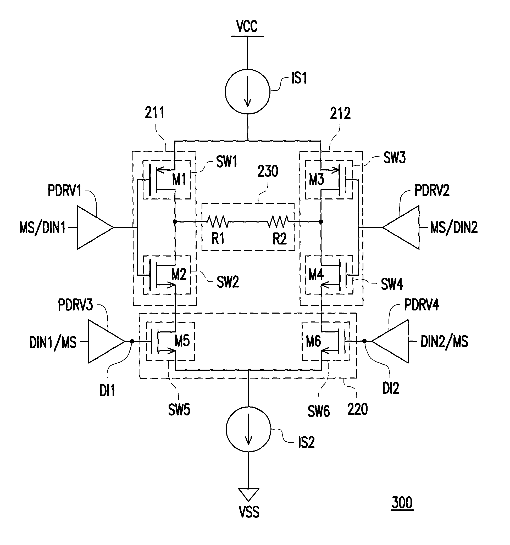
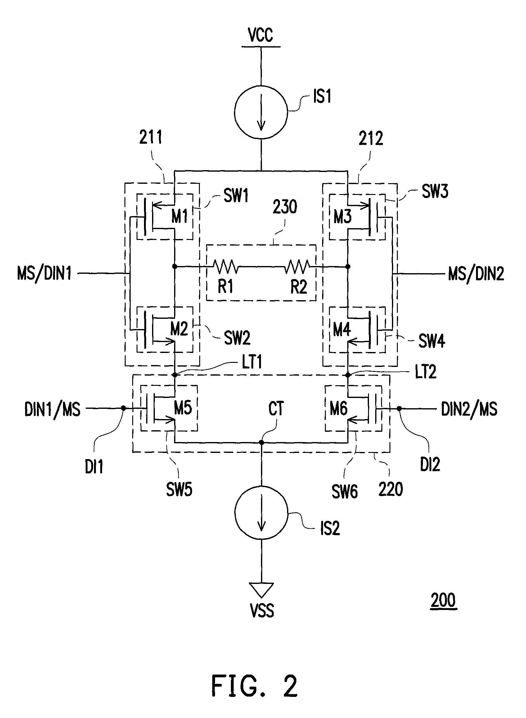
[0024]Referring to FIG. 2, FIG. 2 is a schematic diagram of a dual mode serial transmission apparatus according to an embodiment of the invention. The dual mode serial transmission apparatus 200 includes current sources IS1 and IS2, inverting circuits 211 and 212, a differential pair 220 and a resistor string 230. The current source IS1 is coupled between an operating power VCC and the inverting circuits 211 and 212, and the current source IS1 provides a current to flow to the inverting circuits 211 and 212. The inverting circuit 211 is coupled between the current source IS1 and a load terminal LT1 of the differential pair 220, and the inverting circuit 211 receives a mode selecting signal MS or a first data transmission signal DIN1. Moreover, the inverting circuit 212 is coupled between the current source IS1 and a load terminal LT2 of the differential pair 220, and the inverting circuit 212 receives the mode selecting signal MS or a second data transmission signal DIN2.

[0025]The d...


PUM


Abstract

A dual mode serial transmission apparatus and method for switching a mode thereof are provided. The dual mode serial transmission apparatus includes a first and second current sources, a first and second inverting circuits, a differential pair and a resistor string. The first inverting circuit receives a mode selecting signal or a first data transmission signal, the second inverting circuit receives the mode selecting signal or a second data transmission signal. First and second load terminals of the differential pair are respectively coupled to the first and second inverting circuits. A common terminal of the differential pair is coupled to the second current source. First and second differential input terminals receive the mode selecting signal or respectively receive the first and second data transmission signals. The resistor string is coupled in series between output terminals of the first and second inverting circuits.

Description

CROSS-REFERENCE TO RELATED APPLICATION[0001]This application claims the priority benefit of Taiwan application serial no. 104103011, filed on Jan. 29, 2015. The entirety of the above-mentioned patent application is hereby incorporated by reference herein and made a part of this specification.BACKGROUND[0002]Technical Field[0003]The invention relates to a dual mode serial transmission apparatus and a method for switching mode thereof.[0004]Related Art[0005]In a serial transmission system constructed through a complementary metal oxide semiconductor (CMOS) manufacturing process, a commonly used mode of a transmitting end includes a low voltage differential signal transmission mode (LVDS) and a current mode logic (CML). Referring to FIG. 1A and FIG. 1B, FIG. 1A and FIG. 1B are circuit diagrams of a LVDS mode serial transmission apparatus and a CML mode serial transmission apparatus. In FIG. 1A, the LVDS mode serial transmission apparatus 110 is composed of current sources IS1, IS2, swi...

Claims


Application Information

Patent Timeline
Patent Type & Authority Patents(United States)
IPC IPC(8): H04L27/00H04B3/21H04B3/32H04B3/23
CPCH04B3/32H04B3/21H04B3/23
Inventor LUO, REN-HONGWANG, YAN-TINGLI, HSIANG-CHICHEN, MU-JUNG
Owner NOVATEK MICROELECTRONICS CORP
Why Eureka
Try Eureka