
Reagent dosing pump assembly

a technology of reagent and pump body, which is applied in the direction of mechanical equipment, exhaust treatment, liquid fuel engines, etc., can solve the problems of reducing agent maximum temperature, affecting the safety of users, and posing a threat to public health, so as to reduce the risk of damage to the pump housing in the event of reagent freezing within the pump housing

Active Publication Date: 2016-12-13
DELPHI TECH IP LTD
View PDF16 Cites 4 Cited by
  • Summary
  • Abstract
  • Description
  • Claims
  • Application Information

AI Technical Summary

Benefits of technology

The patent describes a pump assembly with a cooling system that has three compartments for cooling fluid. The first compartment cools the pump housing through the nozzle portion, while the third compartment cools the pump housing further. The flow guide and jacket support the flow guide in the cavity, and the first and second ports are conveniently located next to each other. The jacket also braces the pump housing to prevent damage. The technical effect of this design is a more efficient cooling system that optimizes cooling of the pump housing and reduces the risk of damage.

Problems solved by technology

It is known that exhaust gases from internal combustion engines contain substances which are harmful to the environment and which can pose a threat to public health.
The maximum temperature at which urea-based reducing agents can be used is somewhat limited.
Urea crystals tend to precipitate when the temperature of the solution is greater than approximately 70° C. Precipitation is undesirable because the precipitates can cause blockages in the delivery system, for example in the small-diameter outlets typically provided in the outlet end of the atomising nozzle.
In addition, the formation of precipitates alters the concentration of the remaining solution, so that the effective quantity of ammonia delivered to the exhaust flow becomes uncertain.
This could lead to inefficient catalysis and an insufficient reduction in NOx emissions.
In these cases, the reagent dosing pump is exposed to higher temperatures, due to the closer proximity of the dosing pump to the engine, and it is more difficult to provide a cooling air flow to the reagent dosing pump.
Accordingly, the risk of the reagent overheating in use is higher than in an under-body arrangement.

Method used


Image

  • Reagent dosing pump assembly
  • Reagent dosing pump assembly
  • Reagent dosing pump assembly

Examples


Embodiment Construction

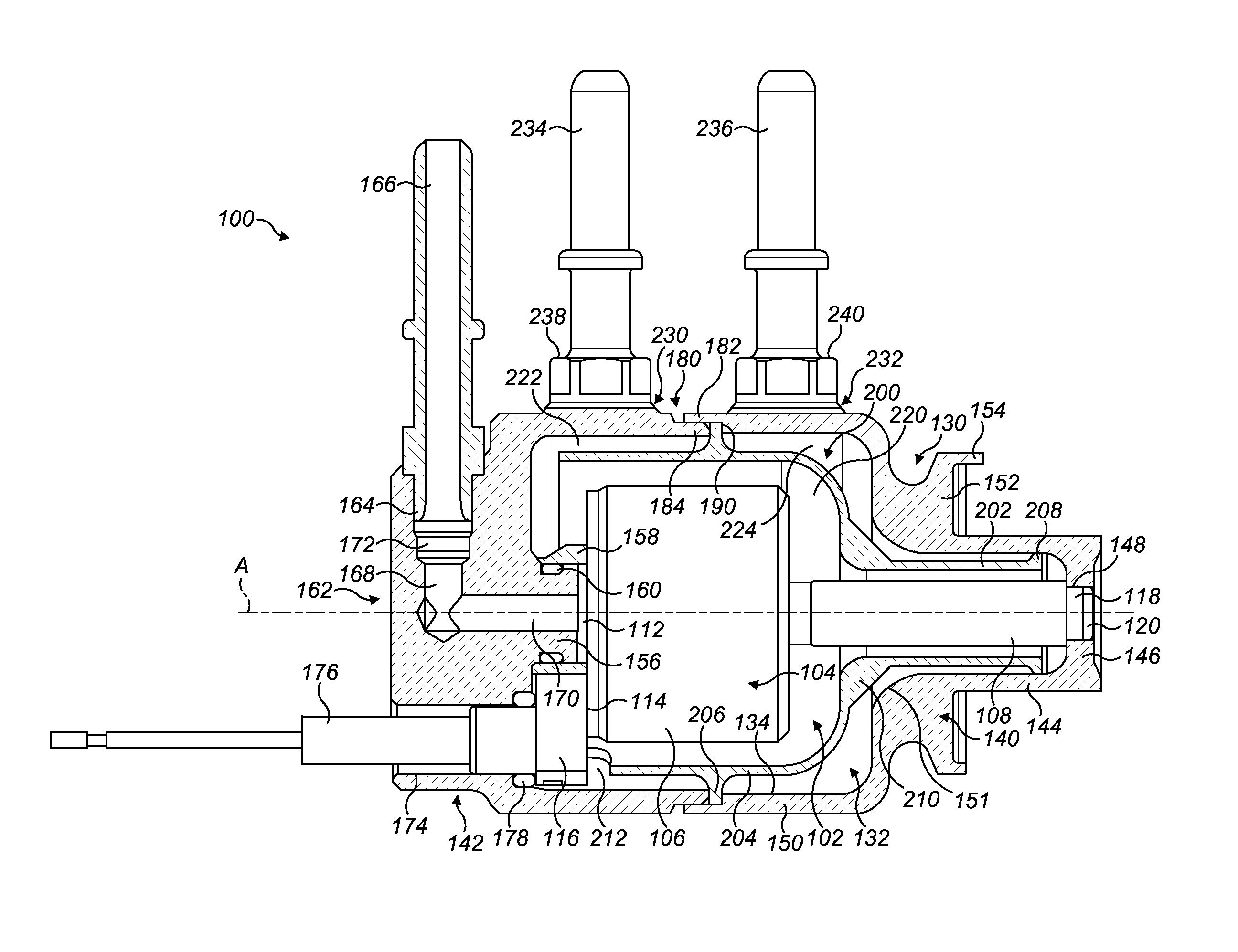
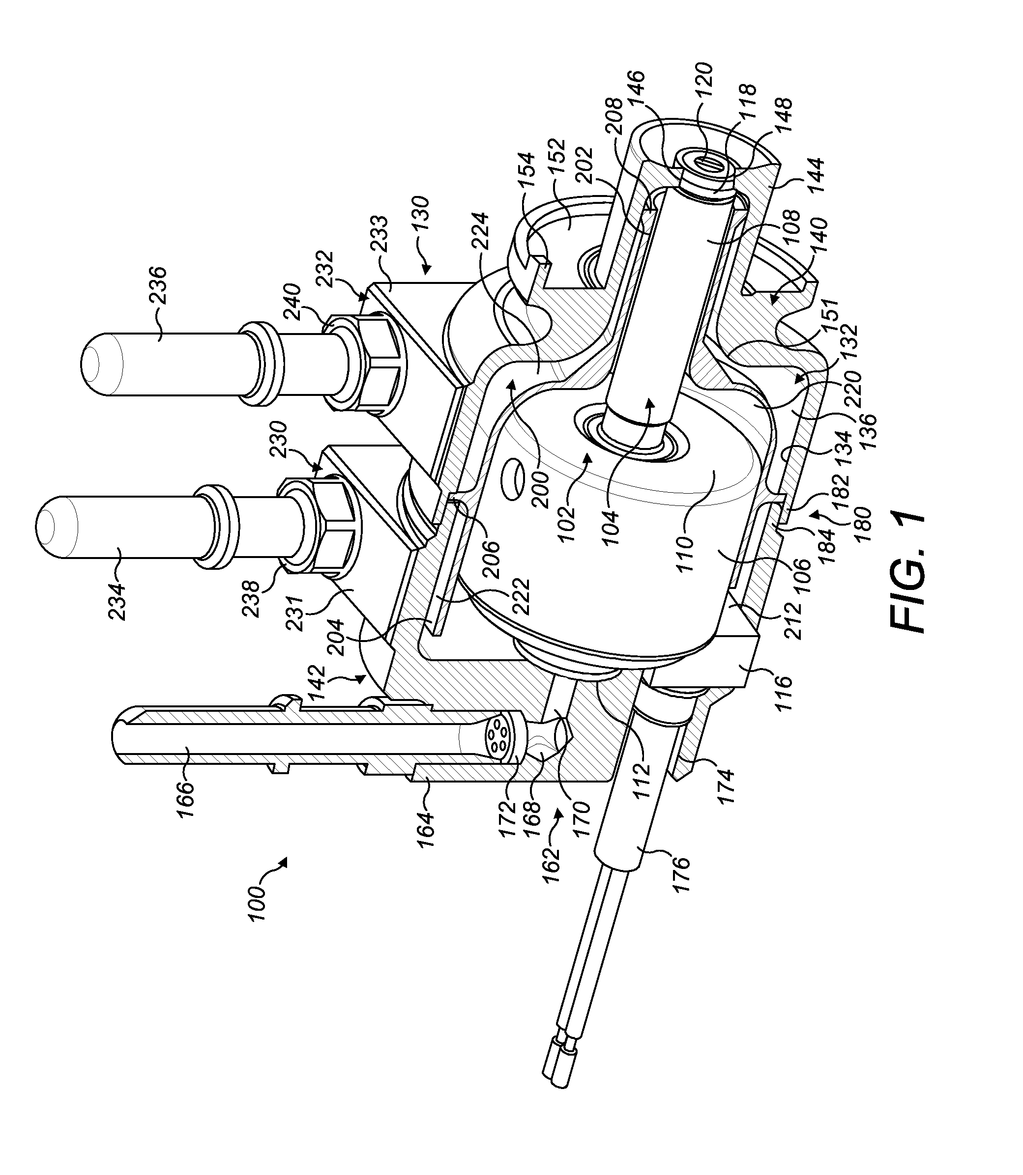
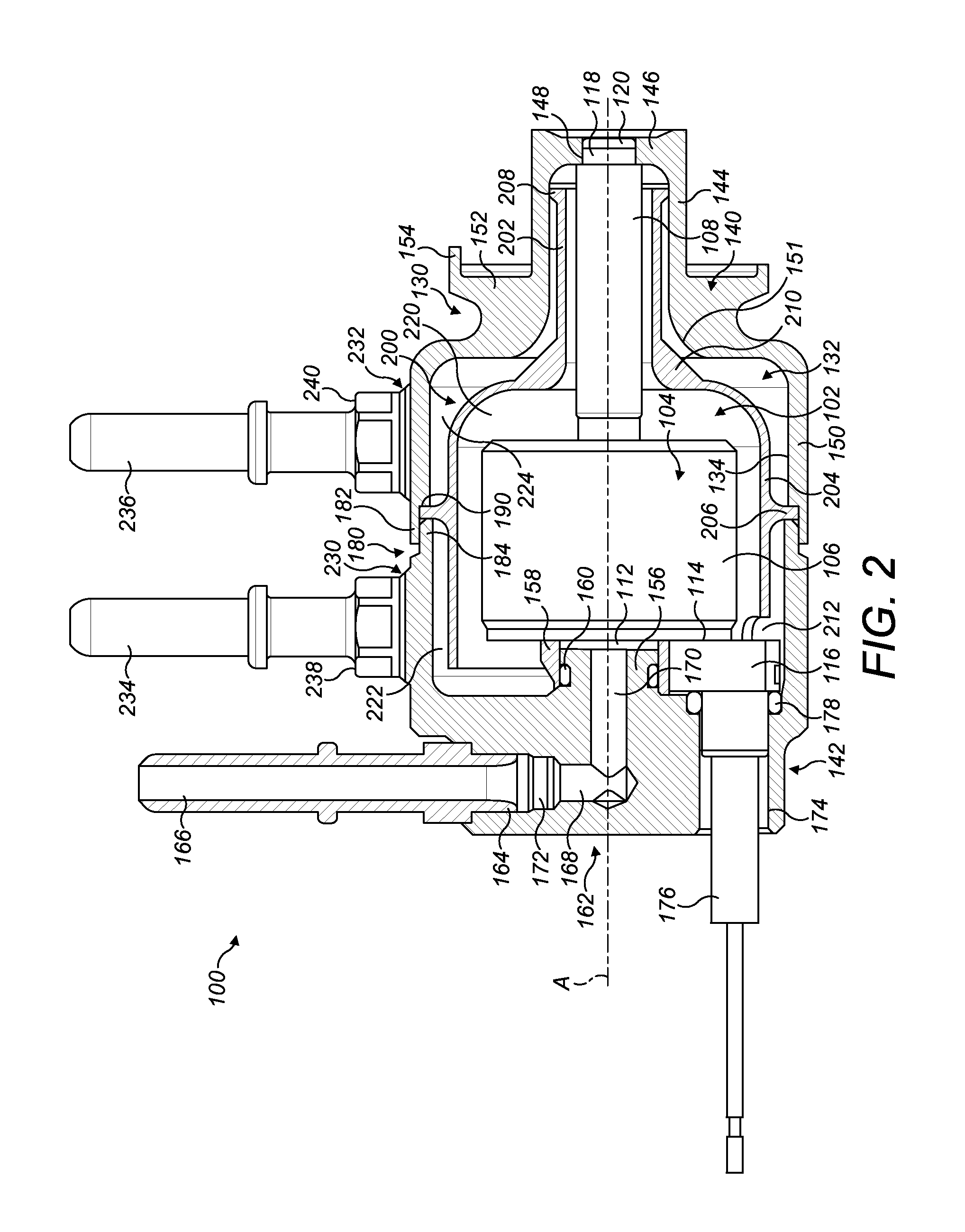
[0040]A pump assembly 100 according to a first embodiment of the present invention is shown in FIGS. 1 to 3.

[0041]Referring first to FIGS. 1 and 2, the pump assembly 100 includes a reagent dosing unit with an integrated pump and nozzle arrangement, referred to hereafter as a reagent dosing pump 102. The pump 102 is a reagent dosing pump of any suitable type, for example as described in EP-A-1878920, to which reference can be made for further details of the pump 102.

[0042]The pump 102 comprises a pump housing 104 having a generally cylindrical pump body portion 106 that defines a pump axis (A in FIG. 2), and a generally cylindrical nozzle portion 108 that extends from a first face 110 of the body portion 106 along the pump axis A. The nozzle portion 108 has a relatively small diameter compared to the body portion 106.

[0043]The body portion 106 of the pump housing 104 houses a pumping mechanism (not shown), such as a solenoid-actuated pumping mechanism. In use, the pumping mechanism r...


PUM


Abstract

A pump assembly having improved cooling for use in a selective catalytic reduction system is disclosed. The pump assembly comprises a pump housing having a body portion and a nozzle portion extending from the body portion, a jacket including a cavity for receiving the pump housing, first and second ports for cooling fluid, and a flow guide disposed between the jacket and the pump housing. The cavity includes a first compartment for cooling fluid defined in part by the flow guide and in part by the pump housing and being in fluid communication with the first port; and a second compartment for cooling fluid defined in part by the flow guide and in part by the jacket. The first compartment is in fluid communication with the second port by way of the second compartment.

Description

CROSS REFERENCE TO RELATED APPLICATIONS[0001]This application is a national stage application under 35 U.S.C. 371 of PCT Application No. PCT / EP2012 / 055141 having an international filing date of 22 Mar. 2012, which designated the United States, which PCT application claimed the benefit of European Patent Application No. 11159223.4 filed 22 Mar. 2011, the entire disclosure of each of which are hereby incorporated herein by reference.FIELD OF THE INVENTION[0002]The present invention relates to a pump assembly with cooling means. More particularly, but not exclusively, the invention relates to a dosing pump for a selective catalytic reduction system with a cooling jacket arrangement.BACKGROUND TO THE INVENTION[0003]It is known that exhaust gases from internal combustion engines contain substances which are harmful to the environment and which can pose a threat to public health. For many years, a sustained effort has been made within the automotive industry to reduce the release to the a...

Claims


Application Information

Patent Timeline
Patent Type & Authority Patents(United States)
IPC IPC(8): F04D29/58F01N3/20
CPCF04D29/58F01N3/2066F01N2610/02F01N2610/11F01N2610/1433F01N2610/1453Y02T10/24Y02T10/12
Inventor WRIGHT, KEITH E.COOKE, MICHAEL PETERNEEDHAM, DAVID W.HARDY, MARTIN PAUL
Owner DELPHI TECH IP LTD
Learn More