Internal combustion engine

a combustion engine and internal combustion technology, applied in the direction of machines/engines, mechanical appliances, pressure lubrication, etc., can solve the problems of inability to cool the bore, inability to reduce the temperature of the central portion of the piston, undesirable increase in oil consumption, etc., to achieve the effect of reducing the temperature of the ring groove, preventing fixation and the like of the ring, and maximizing the cooling of the bor

Inactive Publication Date: 2012-09-18
TOYOTA JIDOSHA KK
View PDF13 Cites 4 Cited by
  • Summary
  • Abstract
  • Description
  • Claims
  • Application Information

AI Technical Summary

Benefits of technology

[0005]Therefore, the present invention is directed to solving the problems as described above, and an object thereof is to provide an internal combustion engine in which the inside thereof can be uniformly cooled.
[0007]In the internal combustion engine configured in such a manner, the outside of the skirt can be cooled and the bore can be cooled indirectly. As a result, the internal combustion engine can be uniformly cooled.
[0009]Preferably, oil is injected from the oil supply portion to a peripheral portion of the piston in the portion located above the pin boss. In this case, when oil is injected to the outside of the skirt, cooling of the bore can be maximized.
[0010]More preferably, a plurality of the oil supply portions are arranged symmetrically with respect to a center of the piston. In this case, the oil supply portion is arranged symmetrically with respect to a point (on a diagonal line), so that the temperature of the piston can be made uniform and the temperature of a ring groove can be reduced. As a result, fixation and the like of a ring can be prevented.

Problems solved by technology

With the conventional art, however, it is difficult to cool a bore although the temperature of the central portion of the piston can be reduced because the oil is injected to the inside of the piston skirt.
If the oil is directly injected to the bore in order to cool the bore, the consumption of oil is undesirably increased.

Method used


Image

  • Internal combustion engine
  • Internal combustion engine
  • Internal combustion engine

Examples


first embodiment

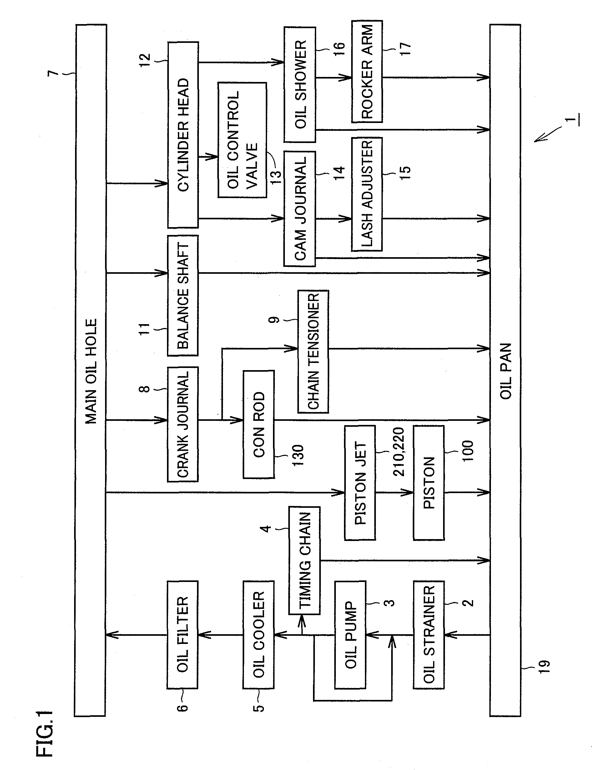
[0052]FIG. 1 is a diagram for explaining a hydraulic circuit of an internal combustion engine according to a first embodiment. Referring to FIG. 1, in the hydraulic circuit of an engine 1 serving as the internal combustion engine, oil is stored in an oil pan 19 provided at the lower part of an engine block. The oil stored in oil pan 19 is supplied to an oil pump 3 through an oil strainer 2 for removing foreign substances. Oil pump 3 is driven by motive power of the engine and pressurizes the oil. The pressurized oil is cooled in an oil cooler 5. The cooled oil is filtered by an oil filter 6. A part of the oil drained out of oil pump 3 lubricates a timing chain 4 and is returned to oil pan 19.

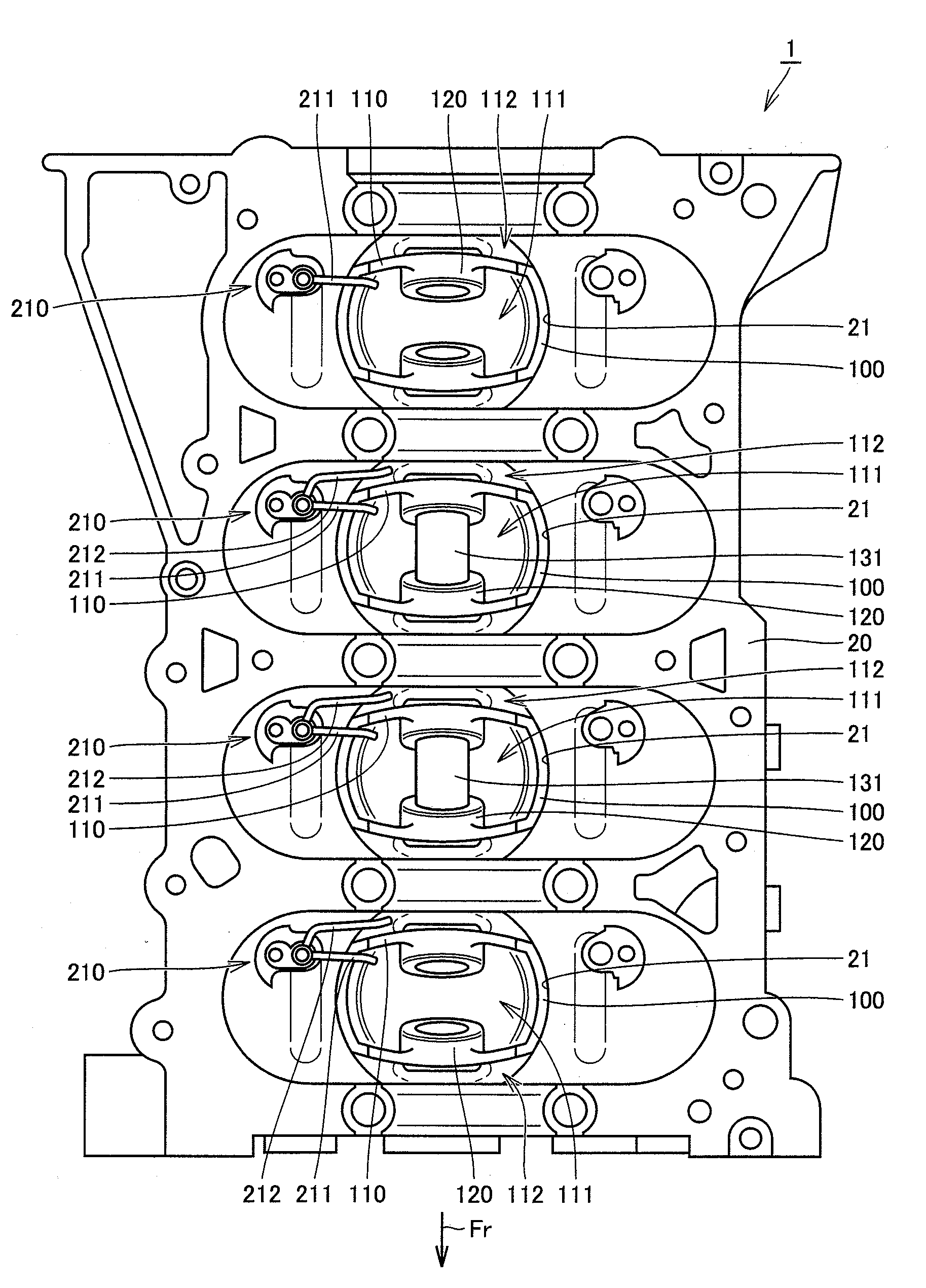
[0053]The oil having passed through oil filter 6 and having the oil pressure applied is supplied to a main oil hole 7. Main oil hole 7 extends to various parts in the engine. A part of the oil in main oil hole 7 is supplied to piston jets (oil jets) 210 and 220, and furthermore, injected toward ...

second embodiment

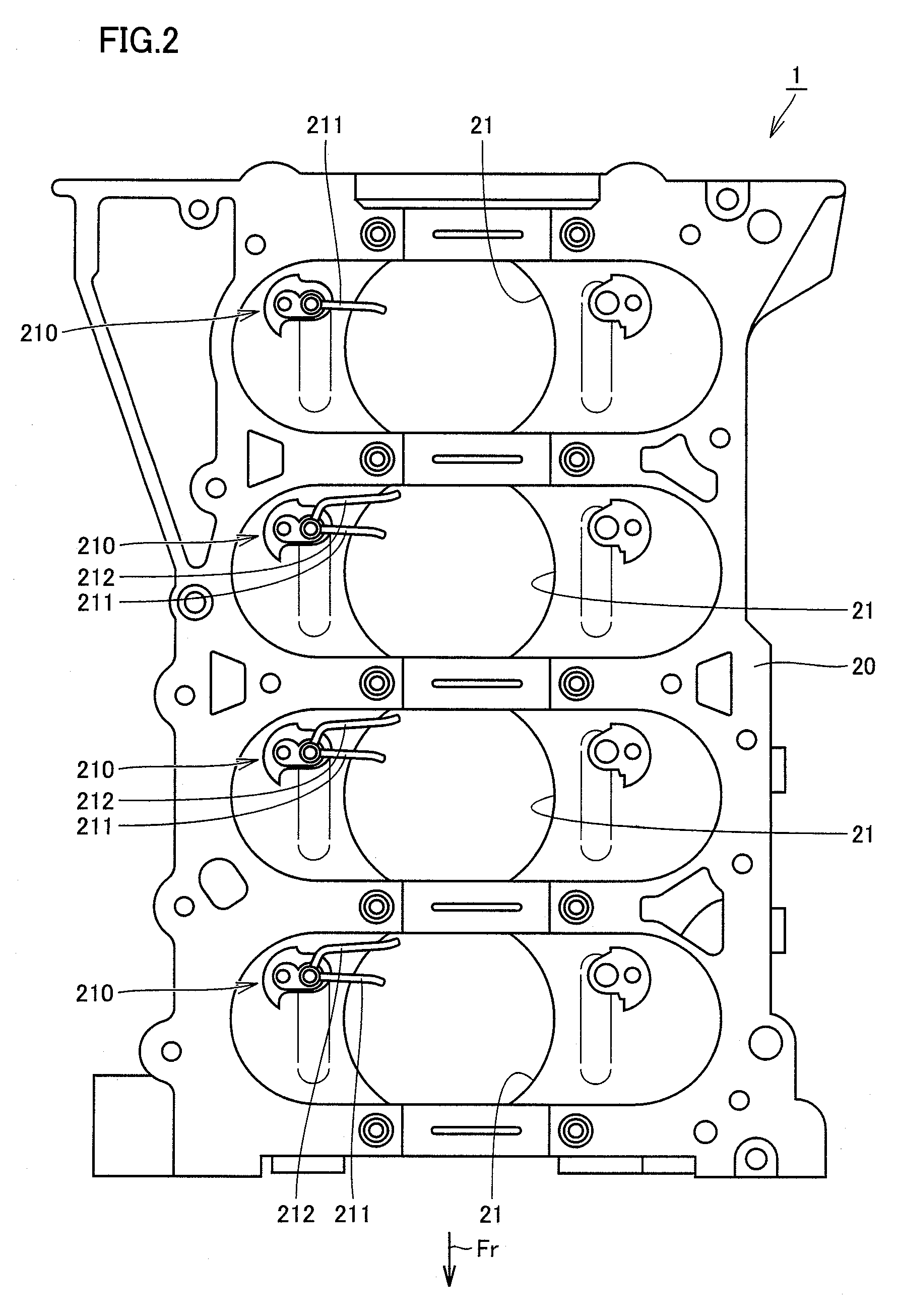
[0069]FIG. 8 is a cross-sectional view of a piston at the top dead center and at the bottom dead center in an internal combustion engine according to a second embodiment. FIG. 9 is a bottom view of the piston at the top dead center as seen from the direction shown by an arrow IX in FIG. 8. Referring to FIGS. 8 and 9, as shown in FIG. 9, an engine 1 according to the second embodiment is different from engine 1 according to the first embodiment in that front-side oil jet 220 and rear-side oil jet 210 serving as two oil supply portions are provided at one piston 100. Front-side oil jet 220 has one front-side nozzle 221. Oil is injected from front-side nozzle 221 toward the direction shown by an arrow 2210 and the oil collides with piston 100 in an injection region 2211. The oil collides in skirt outer region 112 in piston100. Oil is injected from bifurcated front-side nozzle 211 and rear-side nozzle 212 in the directions shown by arrows 2110 and 2120 to skirt inner region 111 and skirt...

third embodiment

[0084]FIG. 23 is a bottom view of an internal combustion engine according to a third embodiment. Referring to FIG. 23, in an engine 1 according to the third embodiment, rear-side oil jet 210 and a front-side oil jet 3210 are arranged symmetrically with respect to a center point 100C of piston 100. Front-side oil jet 3210 has a front-side nozzle 3211 and a rear-side nozzle 3212. Oil is injected from the respective nozzles in the directions shown by arrows 3110 and 3120 to injection regions 3111 and 3121.

[0085]In such engine 1, the inside thereof can be cooled more uniformly.


PUM


Abstract

There is provided an internal combustion engine in which the inside thereof is uniformly cooled. In an engine serving as the internal combustion engine, a piston reciprocates within a bore provided in a cylinder block, and a connecting rod coupled to the piston transmits motive power to a crankshaft. The internal combustion engine includes a rear-side oil jet through which oil is injected from the connecting rod side of the piston to a skirt inner region and a skirt outer region of the piston.

Description

TECHNICAL FIELD[0001]The present invention relates to an internal combustion engine, and more particularly, to an internal combustion engine lubricated with oil.BACKGROUND ART[0002]Conventionally, internal combustion engines are disclosed in, for example, Japanese Patent Laying-Open No. 2003-301744 (Patent Document 1), Japanese Patent Laying-Open No. 9-49456 (Patent Document 2) and Journal of Technical Disclosure No. 91-6590 (Non-patent Document 1).DISCLOSURE OF THE INVENTION[0003]As to conventional internal combustion engines, Patent Document 1, for example, discloses a configuration in which oil is injected from two oil jets to the inside of a piston skirt. Specifically, Patent Document 1 discloses the art of providing nozzles from which oil is injected toward the crankshaft side of a piston.[0004]With the conventional art, however, it is difficult to cool a bore although the temperature of the central portion of the piston can be reduced because the oil is injected to the inside ...

Claims


Application Information

Patent Timeline
Patent Type & Authority Patents(United States)
IPC IPC(8): F01P1/06
CPCF01M1/08F01P3/08F01M2001/086
Inventor ABE, TOMOAKI
Owner TOYOTA JIDOSHA KK
Why Eureka
Try Eureka