Digital movement measuring device

Active Publication Date: 2016-12-13
ARNOLD BERTRAND +2
View PDF21 Cites 0 Cited by
  • Summary
  • Abstract
  • Description
  • Claims
  • Application Information

AI Technical Summary

Benefits of technology

The patent text describes a technology that reduces the time and power needed to calculate the position of a mobile element, such as an optical member. This means that data can be transmitted more quickly and easily. Overall, the technology makes it easier to determine the position of the optical member.

Problems solved by technology

Such a device has disadvantages, in particular conversion of all of the analog information from the sensor into digital data.
Analog noise is added to the errors and to the digital conversion noise.
This undesirable noise limits the dynamic (signal to noise ratio) of the measured signal.
Furthermore, conversion necessitates a non-negligible calculation time and a non-negligible calculation capacity.
In particular, when the device is used in a microphone, the background noise and analog-digital conversion are considered the main factors limiting the dynamic.

Method used


Image

  • Digital movement measuring device
  • Digital movement measuring device
  • Digital movement measuring device

Examples


Embodiment Construction

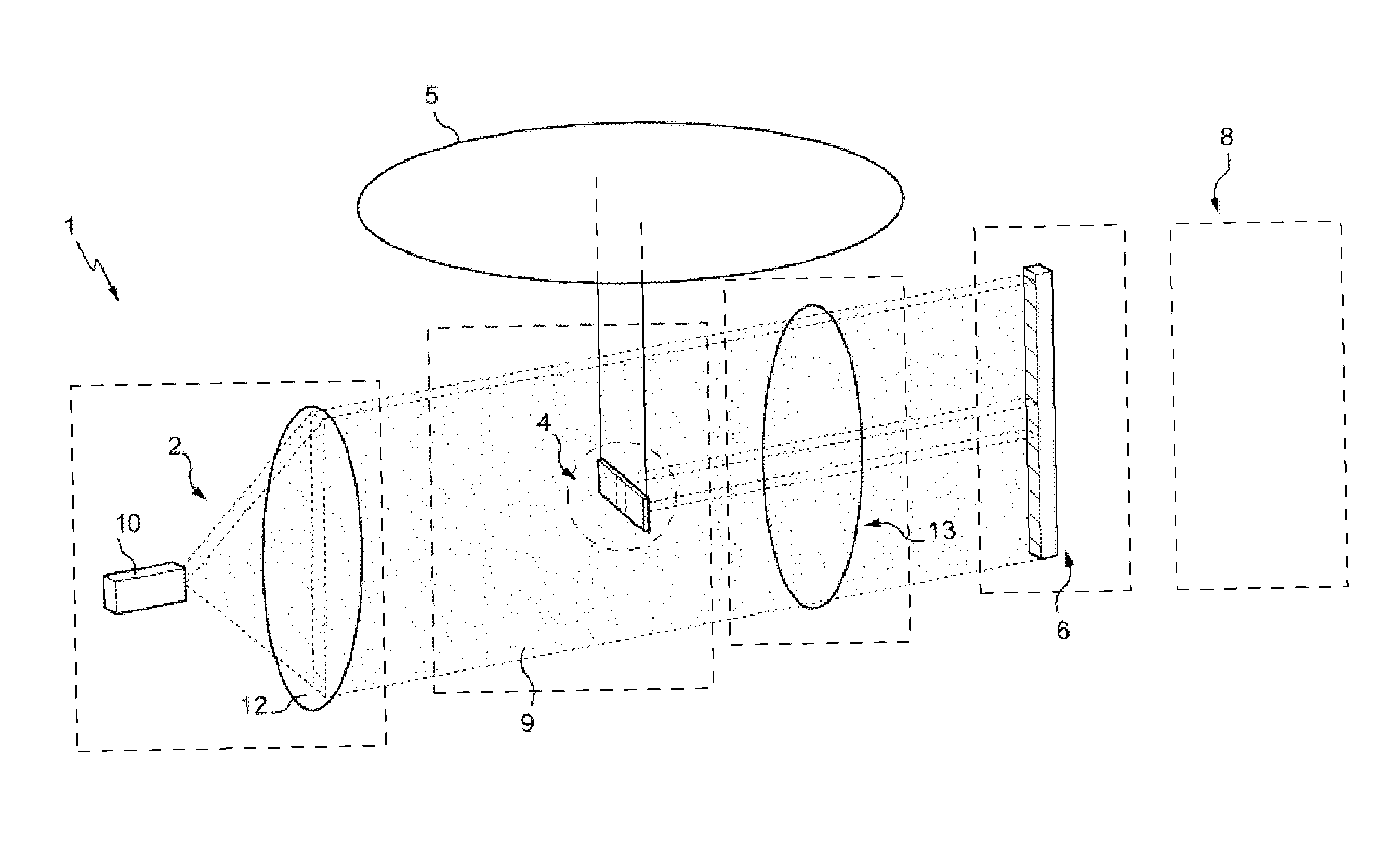
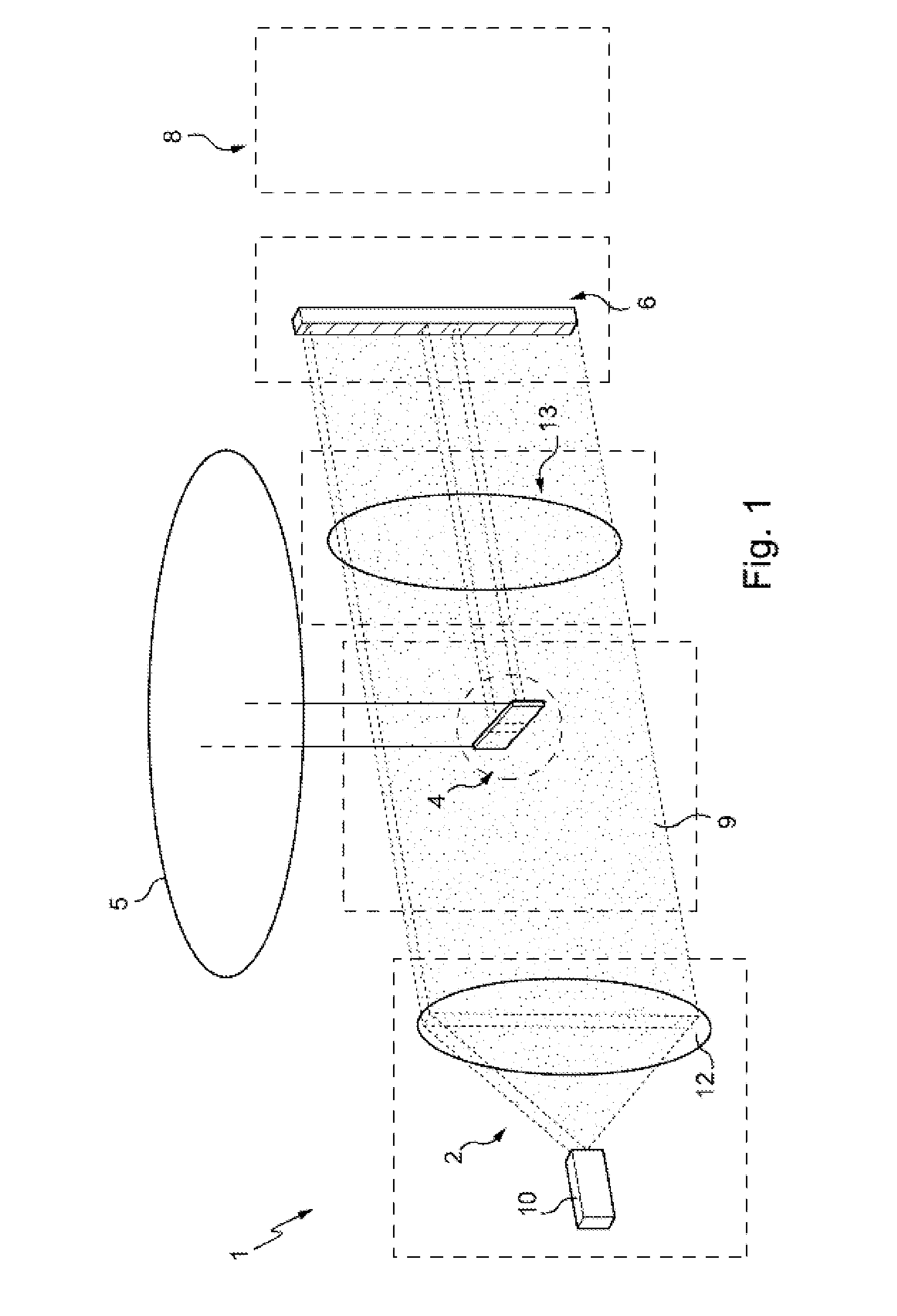
[0073]The movement measurement device 1 shown by way of example in FIG. 1 includes at least one light source 2, an optical member 4 connected to a mobile part 5 of the element the movement of which is to be measured, a sensor 6, and analysis means 8 (represented diagrammatically here and not in its final implementation form).

[0074]The light source 2 creates a fixed light beam 9 following an optical path in order to be captured by the sensor 6.

[0075]The light source 6 is notably able to emit at least one wavelength adapted to the sensitivity of the sensor, likewise its power, in order to exploit a large part of its dynamic range.

[0076]The light beam 9 that it generates is preferably of homogeneous intensity in space and constant intensity in the measurement time of the sensor 6.

[0077]Alternatively, the light beam 9 may be more intense in some particular areas.

[0078]In the embodiment shown in FIG. 1, the light source is a line generator laser 10. Other solutions may be envisaged, howe...


PUM


Abstract

A device for measuring movement of a mobile element moving in at least one direction, includes:a light source adapted to emit a light beam;at least one optical member intercepting the light beam and attached to the mobile element to track its movement;pixel type sensors capturing the transmitted beam determined by the relative position of the optical member relative to the light source, the pixels being disposed so that at least some of them receive illumination that varies with the position of the mobile element as it moves;a comparator module comparing the values obtained from the pixels of the sensors with two distinct thresholds in order to assign some of them a logic value;a calculation module determining the position of the mobile element from the data from the comparator module.

Description

[0001]The invention relates to movement measurement device. Here the concept of movement measurement encompasses the measurement of a position relative to a reference position. As a general rule, a movement measurement device stores analog information from a sensor, converts it into digital data, and transmits it to a computer in order for the movement measurement to be processed.BACKGROUND OF THE INVENTION[0002]A movement measurement device utilizing an optical sensor is described in the document US 2009 / 0248351. A mobile element moves in a direction perpendicular to the direction of emission of a light beam and a linear optical sensor with a pixel array of CCD (Charge-Coupled Device) type or CMOS (Complementary Metal Oxide Semiconductor) type stores the data obtained in this way relating to the luminous flux transmitted and partially blocked by the mobile element. The analog information from the sensors is converted into digital data that is integrated into a calculation module th...

Claims


Application Information

Patent Timeline
IPC IPC(8): G01B11/14G01D5/34
CPCG01B11/14G01D5/342
Inventor ARNOLD, BERTRAND
Owner ARNOLD BERTRAND
Why Eureka
Try Eureka