Polishing apparatus

a technology of polishing apparatus and rotary joint, which is applied in the direction of metal-working apparatus, lapping machines, manufacturing tools, etc., can solve the problems of torsional vibration in the rotary joint, poor film coating performance (step coverage), and large steps, and achieve the effect of stable operation of the apparatus

Active Publication Date: 2016-12-20
EBARA CORP
View PDF18 Cites 1 Cited by
  • Summary
  • Abstract
  • Description
  • Claims
  • Application Information

AI Technical Summary

Benefits of technology

[0009]According to an embodiment, there is provided a polishing apparatus which can continue stable operation of the apparatus without generating torsional vibration in a rotary joint and without generating an abnormal sound at an engagement part between a cooling water pipe and a polishing table.
[0014]According to the embodiment, since the link mechanism is configured by connecting the two spherical plain bearings, the micro rotational movement in all directions (360°) about each of the centers of the two spherical plain bearings can be made. Further, by arranging axes of the two spherical plain bearings so as to be perpendicular to each other, the centers of the rotational movements of the two spherical plain bearings differ in phase by 90°, and thus the degree of freedom of the movement is increased.
[0017]In an embodiment, the link mechanism is coupled to the rotary joint to increase a natural frequency of the rotary joint, whereby the natural frequency of the rotary joint is different from a natural frequency of a rotating member of the polishing table or a rotating member of the top ring.
[0018]According to the embodiment, by connecting the link mechanism with the rotary joint, a rotary joint assembly which integrates the rotary joint and the link mechanism has an increased natural frequency which is significantly different from natural frequencies of other peripheral parts. Therefore, resonance between the rotary joint assembly, which integrates the rotary joint and the link mechanism, and the peripheral parts such as a cooling water pipe can be prevented. As a result, the torsional vibration of the rotary joint can be prevented, and the pipe wear and the generation of the abnormal sound can be prevented.
[0020]According to the above-described embodiments, stable operation of the apparatus can be continued without generating the torsional vibration in the rotary joint and without generating the abnormal sound at the engagement part between the cooling water pipe and the polishing table.

Problems solved by technology

Multilayer interconnections in smaller circuits result in greater steps which reflect surface irregularities on lower interconnection layers.
An increase in the number of interconnection layers makes film coating performance (step coverage) poor over stepped configurations of thin films.
However, torsional vibration is generated in the rotary joint or an abnormal sound is generated at an engagement part between the cooling water pipe and the polishing table depending on installation environment or operating condition (e.g. at the time of low-speed idling) of the polishing apparatus.
If the operation of the polishing apparatus is continued under this circumstance, a fatigue failure of the above-mentioned parts provided in the cooling water supply passage may be caused or the pipes may be damaged due to sliding wear, possibly leading to leakage of the cooling water.

Method used


Image

  • Polishing apparatus
  • Polishing apparatus
  • Polishing apparatus

Examples


Embodiment Construction

[0030]A polishing apparatus according to an embodiment will be described below with reference to FIGS. 1 through 9. Like or corresponding parts are denoted by like or corresponding reference numerals in FIGS. 1 through 9 and will not be described below repetitively. In this embodiment, a semiconductor wafer will be described as a substrate to be polished.

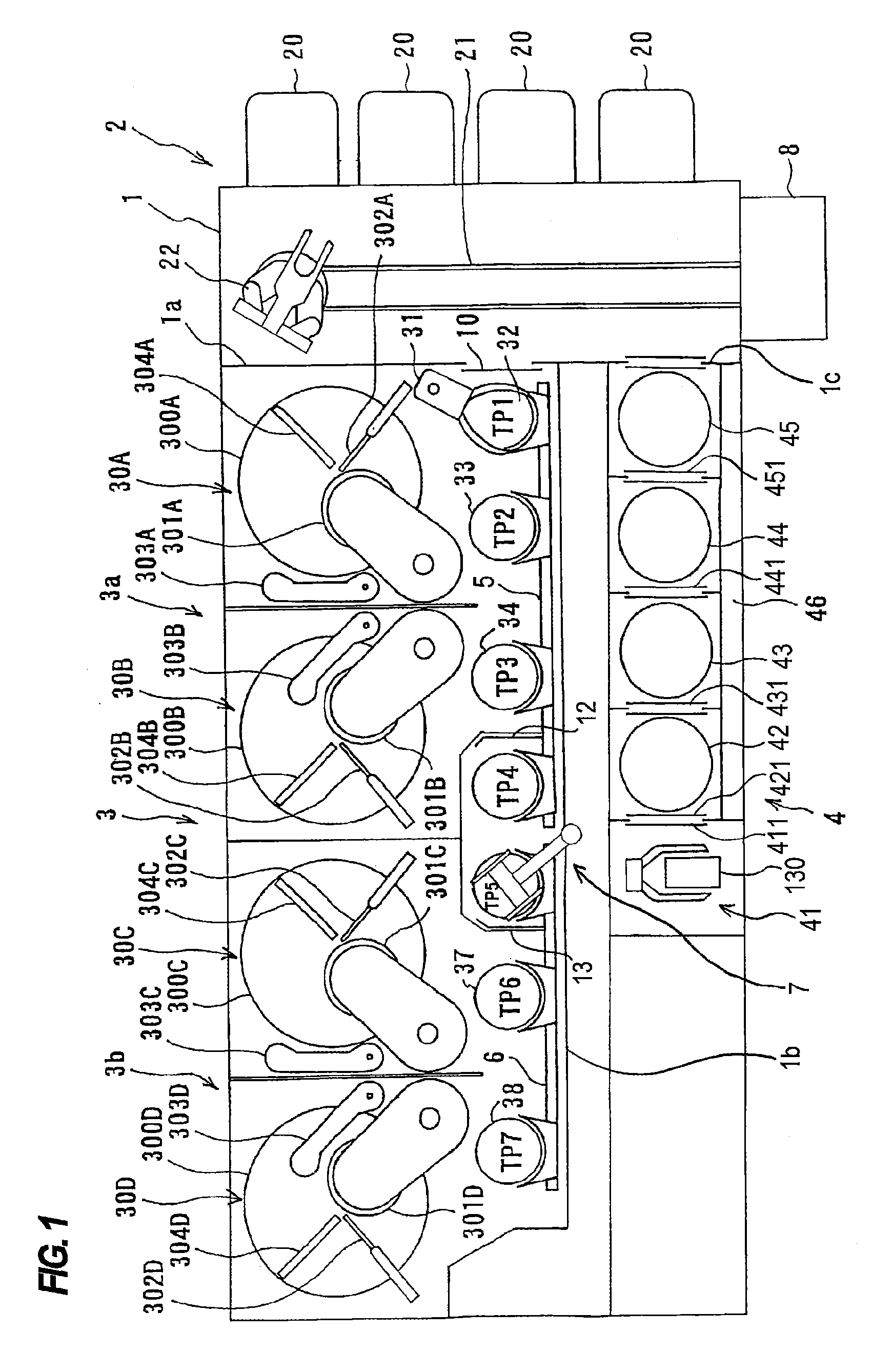
[0031]FIG. 1 is a plan view showing an entire structure of a polishing apparatus according to the embodiment. As shown in FIG. 1, the polishing apparatus according to the embodiment has a housing 1 in a generally-rectangular shape. An interior space of the housing 1 is divided into a loading / unloading section 2, a polishing section 3 (3a, 3b), and a cleaning section 4 by partition walls 1a, 1b and 1c. The loading / unloading section 2, the polishing sections 3a, 3b, and the cleaning section 4 are assembled independently of each other, and air is discharged from these sections independently of each other.

[0032]The loading / unloading sec...


PUM


Abstract

A polishing apparatus which can continue stable operation of the apparatus without generating torsional vibration in a rotary joint and without generating an abnormal sound at an engagement part between a cooling water pipe and a polishing table is disclosed. The polishing apparatus includes a rotary joint fixed to a rotating part of the polishing table or a rotating part of the top ring to supply a fluid into the polishing table or the top ring and discharge the fluid from the polishing table or the top ring, and a rotation-prevention mechanism which connects the rotary joint with an apparatus frame to prevent the rotary joint from being rotated. The rotation-prevention mechanism includes a link mechanism having at least one spherical plain bearing.

Description

CROSS REFERENCE TO RELATED APPLICATION[0001]This document claims priority to Japanese Patent Application Number 2014-141732 filed Jul. 9, 2014, the entire contents of which are hereby incorporated by reference.BACKGROUND[0002]In recent years, high integration and high density in semiconductor device demands smaller and smaller wiring patterns or interconnections and also more and more interconnection layers. Multilayer interconnections in smaller circuits result in greater steps which reflect surface irregularities on lower interconnection layers. An increase in the number of interconnection layers makes film coating performance (step coverage) poor over stepped configurations of thin films. Therefore, better multilayer interconnections need to have the improved step coverage and proper surface planarization. Further, since the depth of focus of a photolithographic optical system is smaller with miniaturization of a photolithographic process, a surface of the semiconductor device ne...

Claims


Application Information

Patent Timeline
Patent Type & Authority Patents(United States)
IPC IPC(8): B24B37/015B24B37/10B24B37/04
CPCB24B37/015B24B37/04B24B37/107
Inventor AIZAWA, HIDEOUMEMOTO, MASAOSONE, TADAKAZUKOSUGE, RYUICHI
Owner EBARA CORP
Why Eureka
Try Eureka