Floatable transportation and installation structure for transportation and installation of a floating wind turbine, a floating wind turbine and method for transportation and installation of the same

Active Publication Date: 2016-12-20
MECAL WIND TURBINE DESIGN
View PDF32 Cites 3 Cited by
  • Summary
  • Abstract
  • Description
  • Claims
  • Application Information

AI Technical Summary

Benefits of technology

[0058]The floating wind turbine preferably further comprises a floating support structure and at least one wind turbine arrangement attached to the floating support structure, wherein the floating support structure is not comprising ballasting and de-ballasting means and is especially not ballastable and de-ballastable by taking and/or ejecting water or similar ballast means. Although transporting a floating turbine with a TLP support structure and installing and anchoring it at the designated site is complex and laborious, by use of the aforementioned floatable transportation and installation structure, easy transport and installation is possible, resulting in a very economical production of wind turbines.
[0059]Preferably the floating wind turbine comprises attachment means for at least temporarily attaching some or all of the fixation means, by which the floating wind turbine can be fixed at an installation position offshore, during transportati

Problems solved by technology

However, due to the nature of the water and the weather conditions, the assembly and installation of offshore wind turbines has proved to be difficult and expensive.
The need for specialist vessels, lifting devices and offshore cranes adds significantly to the overall expense of an offshore wind farm.
The largest expense is the cost of the pre-installed offshore foundations and their installation.
However, this means that semi-submersibles rely on a large water-plane area to stabilize the structure against the changing loads such as those resulting from the operation of the wind turbine.
This requires deep water depths of over 100 m. The structures are also very heavy and costly with the possibility of reduction in weight being highly unlikely.
Due to the length of the spar structure, onshore assembly of the full turbine and support structure is probably not possible which increases the cost further due to the offshore cranes, lifting devices or specialist transport vessels

Method used


Image

  • Floatable transportation and installation structure for transportation and installation of a floating wind turbine, a floating wind turbine and method for transportation and installation of the same
  • Floatable transportation and installation structure for transportation and installation of a floating wind turbine, a floating wind turbine and method for transportation and installation of the same
  • Floatable transportation and installation structure for transportation and installation of a floating wind turbine, a floating wind turbine and method for transportation and installation of the same

Examples


Example

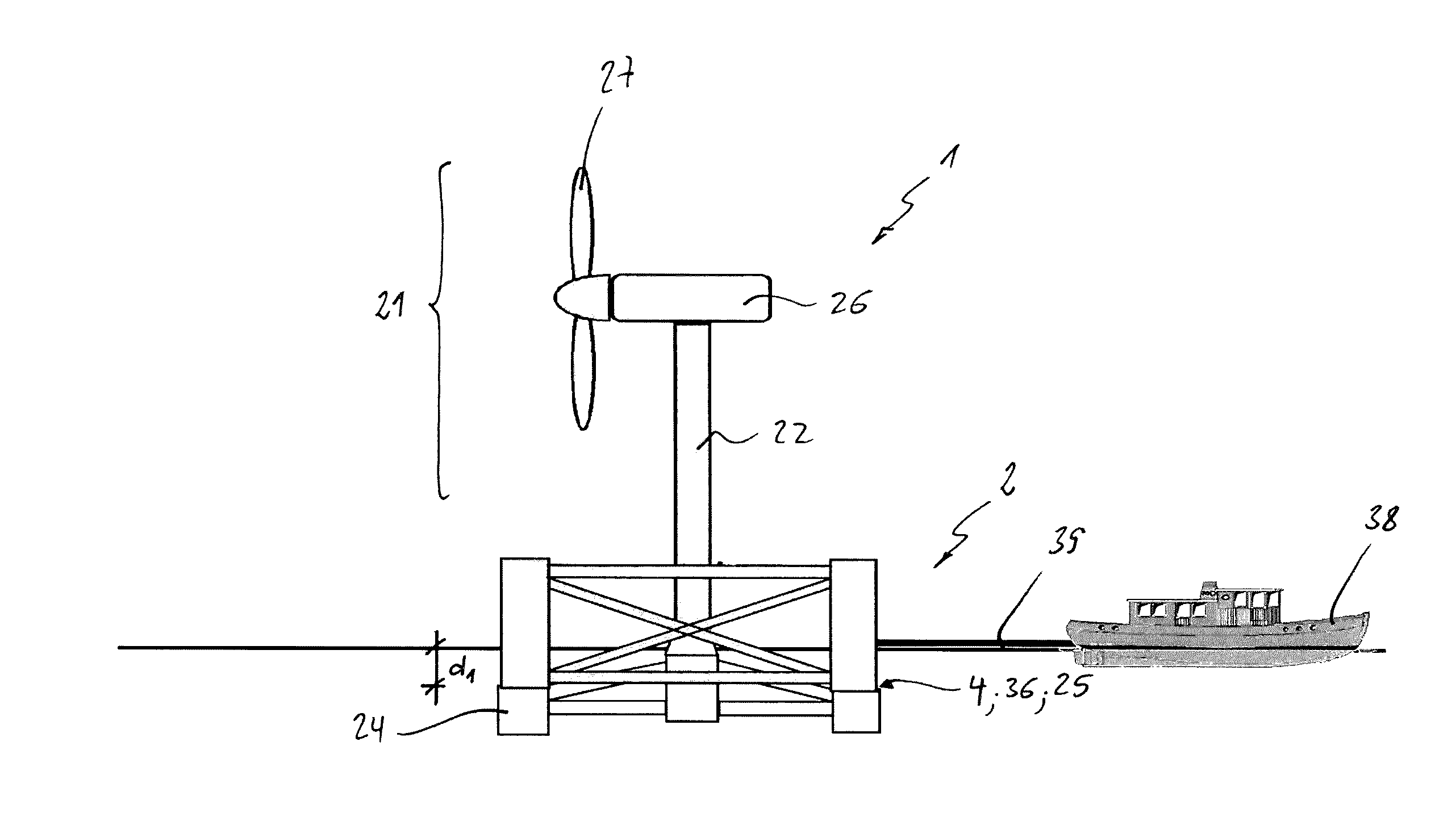
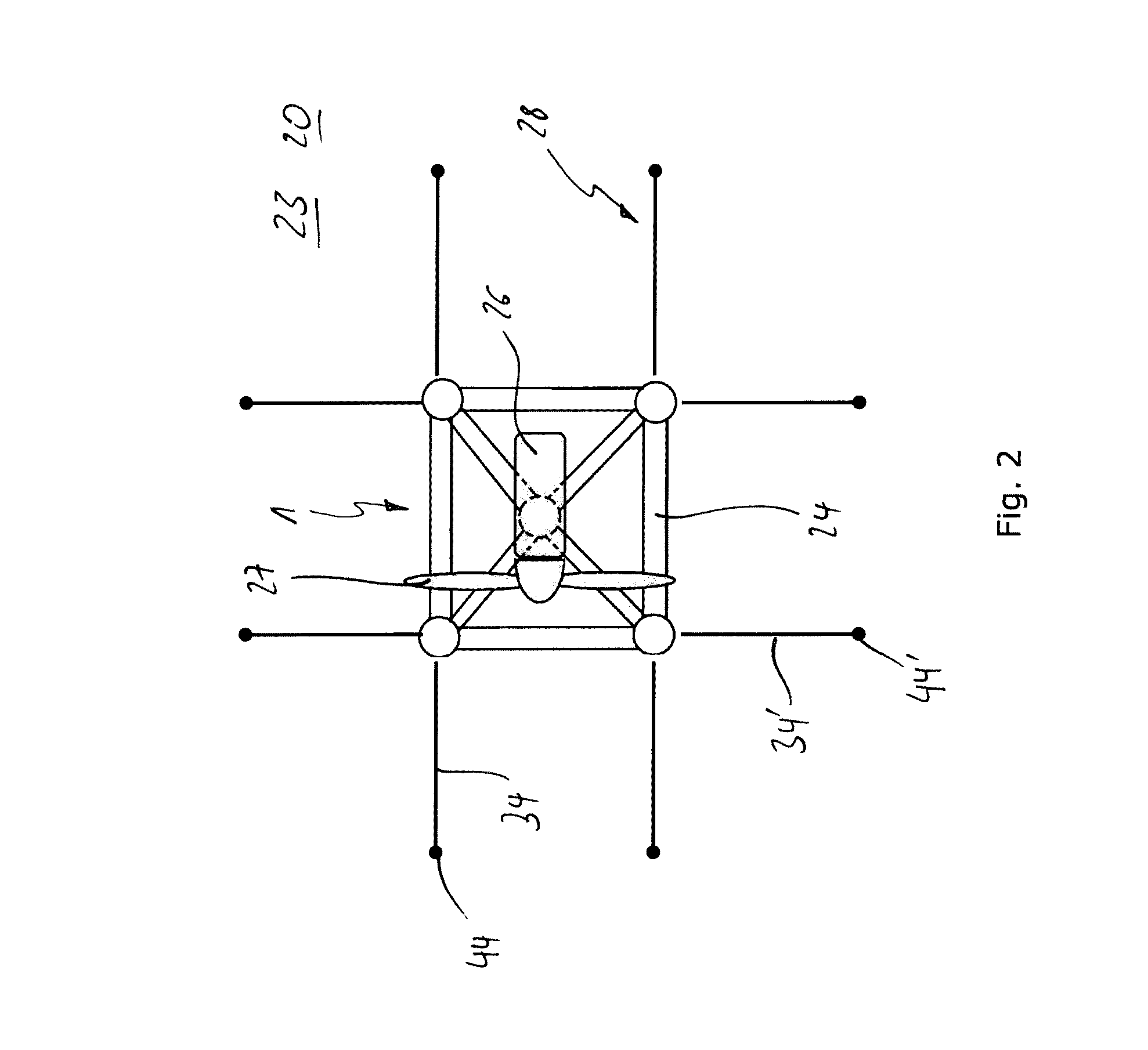
[0102]FIGS. 10-17 are disclosing a second embodiment and especially a second method of transportation and installation wind turbine 1. The basic arrangement of a floatable transportation and installation structure 2 attached to a floatable wind turbine 1 and especially on top 25 of a floating support structure 24 of this wind turbine 1 is identical to the before mentioned embodiment. Therefore, to the before passages is referred for the sake of clarity.

[0103]However, the disclosed arrangement and method respectively differs from the before mentioned in that at least parts of the fixation system 28 are now attached to the arrangement of floatable transportation and installation structure 2 and / or the wind turbine 1 by provided attachment means 29 during transport by the tugboat 38.

[0104]In this special embodiment tendon anchoring means 42 and mooring anchoring means 44 are attached to the floating support structure 24 of the floating wind turbine 1 during transport. Furthermore, it i...

Example

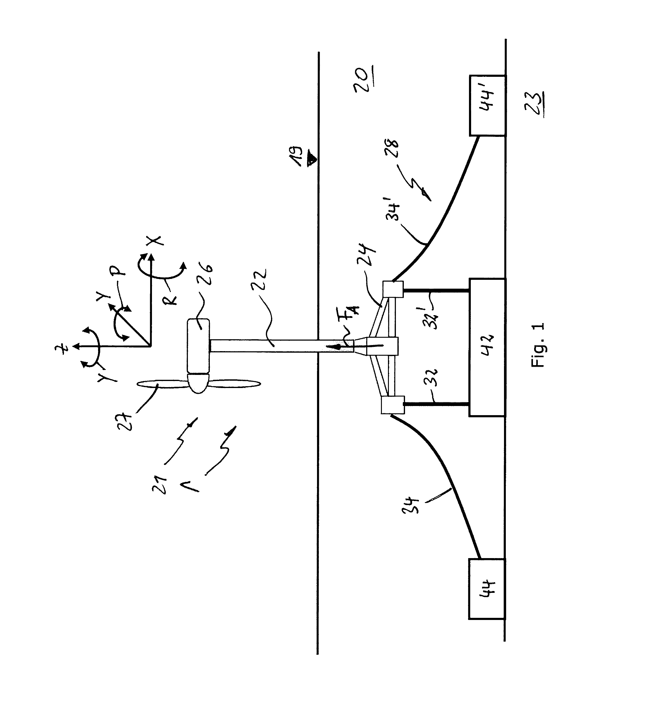
[0109]As described before with regards to the first embodiment described and now again shown in FIGS. 14-17, the floatable transportation and installation structure 2 is detached from the floating wind turbine 1, the de-ballastable floating means 6 are emptied, here e.g. by ejecting water 20, so that the floatable transportation and installation structure 2 lifts up to a floating depth d3 (see FIG. 14).

[0110]Preferably the detaching operation comprises the following steps: ballast water is pumped out of the floatable transportation and installation structure 2 and especially out of the de-ballastable floating means 6 until the floating wind turbine 1 reaches final installation position. Successively, the floatable transportation and installation structure 2 is detached from the floating wind turbine 1, wherein especially the securing and counter securing means 4, 36 are opened. Finally, extra ballast water is ejected from the de-ballastable floating means 6 until the floatable trans...


PUM


Abstract

The present invention relates to a floatable transportation and installation structure for transportation and installation of an essentially fully assembled and erected floating wind turbine, wherein said transportation and installation structure is comprising securing means for detachably and temporarily securing the floatable transportation and installation structure to the erected floating wind turbine in such a way that the floating wind turbine is stabilized and can be moved by moving the transportation and installation structure.
Further, the invention relates to a floating wind turbine comprising securing counter means connectable to securing means of a floatable transportation and installation structure according to the before mentioned kind and to a method of transportation and installation of such a floating wind turbine.

Description

CROSS-REFERENCE TO RELATED APPLICATIONS[0001]This application is the U.S. National Phase of, and Applicants claim priority from, International Patent Application Number PCT / NL2013 / 050790 filed Nov. 5, 2013, which claims priority from NL 2009763 filed Nov. 6, 2012, each of which is incorporated herein by reference.FIELD OF THE INVENTION[0002]The present invention relates to a floatable transportation and installation structure for transportation and installation of an essentially fully assembled and erected floating wind turbine.[0003]Further, the invention relates to such a wind turbine securable to such a floatable transportation and installation structure.[0004]Finally, the invention relates to a method for transportation and installation of an essentially fully assembled and erected floating wind turbine.[0005]In detail, the present invention relates to a transportation and installation method and structure for an offshore wind turbine and in particular to floating offshore wind ...

Claims


Application Information

Patent Timeline
IPC IPC(8): E02B17/00B63B35/44B63B1/10E02D27/52E02D27/50E02B17/04E02B17/02B63B21/50B63B35/00B63B1/12
CPCF03D13/25B63B1/107B63B21/50B63B35/003B63B35/44E02B17/02E02B17/04E02D27/50E02D27/52F03D13/22Y02E10/721B63B2001/128B63B2021/505B63B2035/446E02B2017/0039E02B2017/0047E02B2017/0091E02B2017/0095F05B2240/93F05B2240/95Y02E10/727Y02B10/30B63B77/10Y02E10/72B63B21/502
Inventor TAUB, EYAL MOSHE
Owner MECAL WIND TURBINE DESIGN
Why Eureka
Try Eureka