Conductive wire connection structure of rail-type electrical terminal

a technology of electrical terminals and conductive wires, which is applied in the direction of connections, contact members penetrating/cutting insulation/cable strands, electrical apparatus, etc., can solve the problems of high production cost, high production cost, and low yield of conventional electrical connection terminals, so as to reduce waste material yield, enhance heat dissipation effect, and increase operational and motional stability

Active Publication Date: 2016-12-20
SWITCHLAB +1
View PDF5 Cites 15 Cited by
  • Summary
  • Abstract
  • Description
  • Claims
  • Application Information

AI Technical Summary

Benefits of technology

[0013]It is therefore a primary object of the present invention to provide a conductive wire connection structure of rail-type electrical terminal, which is able to reduce the yield of waste material in manufacturing, enhance heat dissipation effect and increase operational and motional stability in condition of structural simplification. The conductive wire connection structure includes a conductive support mounted in an insulation case. The conductive support is divided into two parts of a U-shaped support main body and a C-shaped wire connector. The wire connector is assembled with a metal leaf spring and disposed on the support main body together with the metal leaf spring for pivotally connecting with the grounding conductive wire coming from a machine or an apparatus. The wire connector and the metal leaf spring are respectively formed with insertion sections for assembling the wire connector with the metal leaf spring to help the support main body to hold the metal leaf spring and prevent the metal leaf spring from deflecting.
[0015]In the above conductive wire connection structure of rail-type electrical terminal, the insertion sections of the wire connector are respectively formed between the second and third sides and between the third and fourth sides in the form of notches. The insertion sections of the metal leaf spring are respectively formed on two sides of the metal leaf spring corresponding to the positions of the insertion sections of the wire connector. The insertion sections of the metal leaf spring are inserted in the notches of the insertion sections of the wire connector to securely assemble the metal leaf spring with the wire connector and help the support main body to hold the metal leaf spring and prevent the metal leaf spring from deflecting.

Problems solved by technology

With respect to the manufacturing, operation and application of the assembling structure of the conventional rail-type electrical connection terminal:1. The conductive support of the conventional electrical connection terminal has a complicated structure and is troublesome and time-consuming to manufacture.
Therefore, the yield can be hardly promoted and a large amount of waste material is produced in the manufacturing process.
Under such circumstance, it is impossible to effectively restrict the motion of the metal leaf spring.
On the contrary, in the case that the conductive support is selectively made of a material with higher rigidity or hardness, (such as iron, steel, etc.), the electrical conductivity will be not idealistic.
That is, it is hard to meet both the requirements of good electrical conductivity and high rigidity or hardness at the same time.
However, it is quite troublesome and time-consuming to manufacture such conductive support and the cost is relatively high.
Still with respect to the manufacturing, operation and application of the assembling structure of the conventional rail-type electrical connection terminal, the structural design for assembling the wire connector with the metal leaf spring is not idealistic.
This leads to that the metal leaf spring can be hardly securely located in the wire connector in a true position.
When the conductive wire is inserted into the case, it often takes place that the bare metal end of the conductive wire thrusts the case or deflects the metal leaf spring to scrape the case or is not stably held due to mass insertion operation and human error.
However, as well known by those who are skilled in this field, the heat generated by the current can be hardly conducted out of a closed wire connector structure.
Not only the material cost of the closed wire connector is relatively high, but also high temperature and high resistance often take place in the closed wire connector to deteriorate the electrical conduction effect.
This improves the shortcomings of the conventional conductive support that the conventional conductive support has a complicated bending structure and is troublesome and time-consuming to manufacture and a large amount of waste material is produced in the manufacturing process.

Method used


Image

  • Conductive wire connection structure of rail-type electrical terminal
  • Conductive wire connection structure of rail-type electrical terminal
  • Conductive wire connection structure of rail-type electrical terminal

Examples


Embodiment Construction

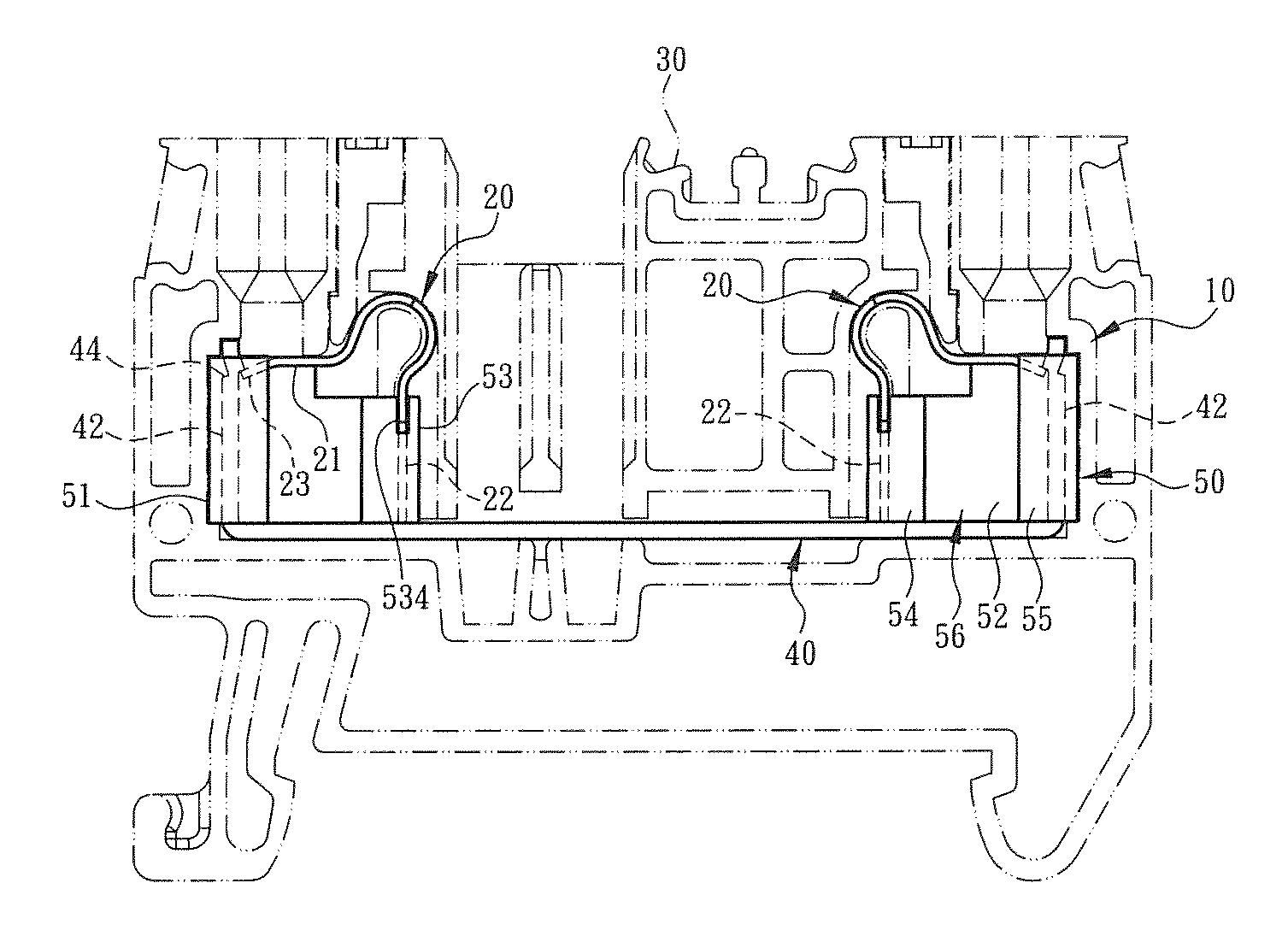
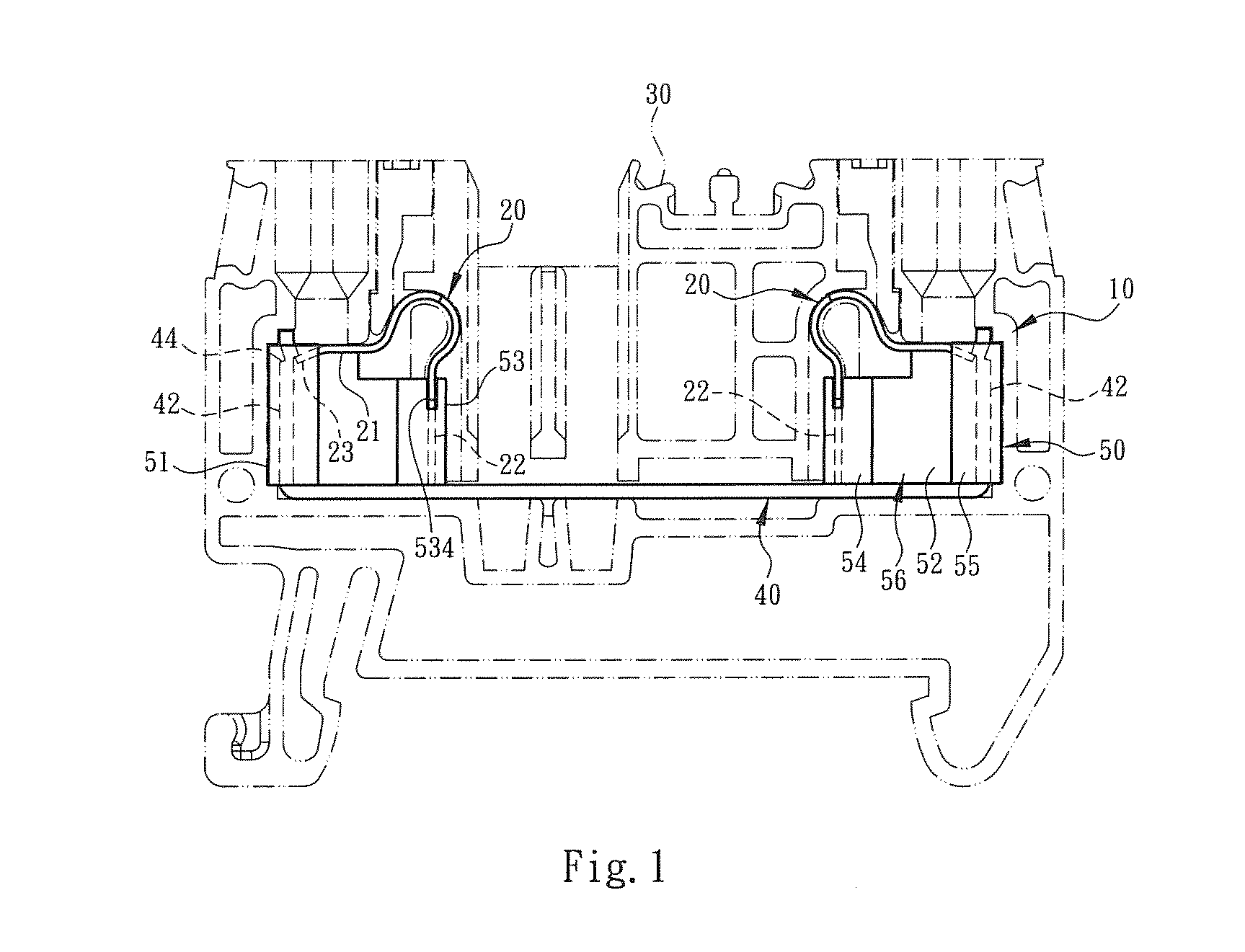
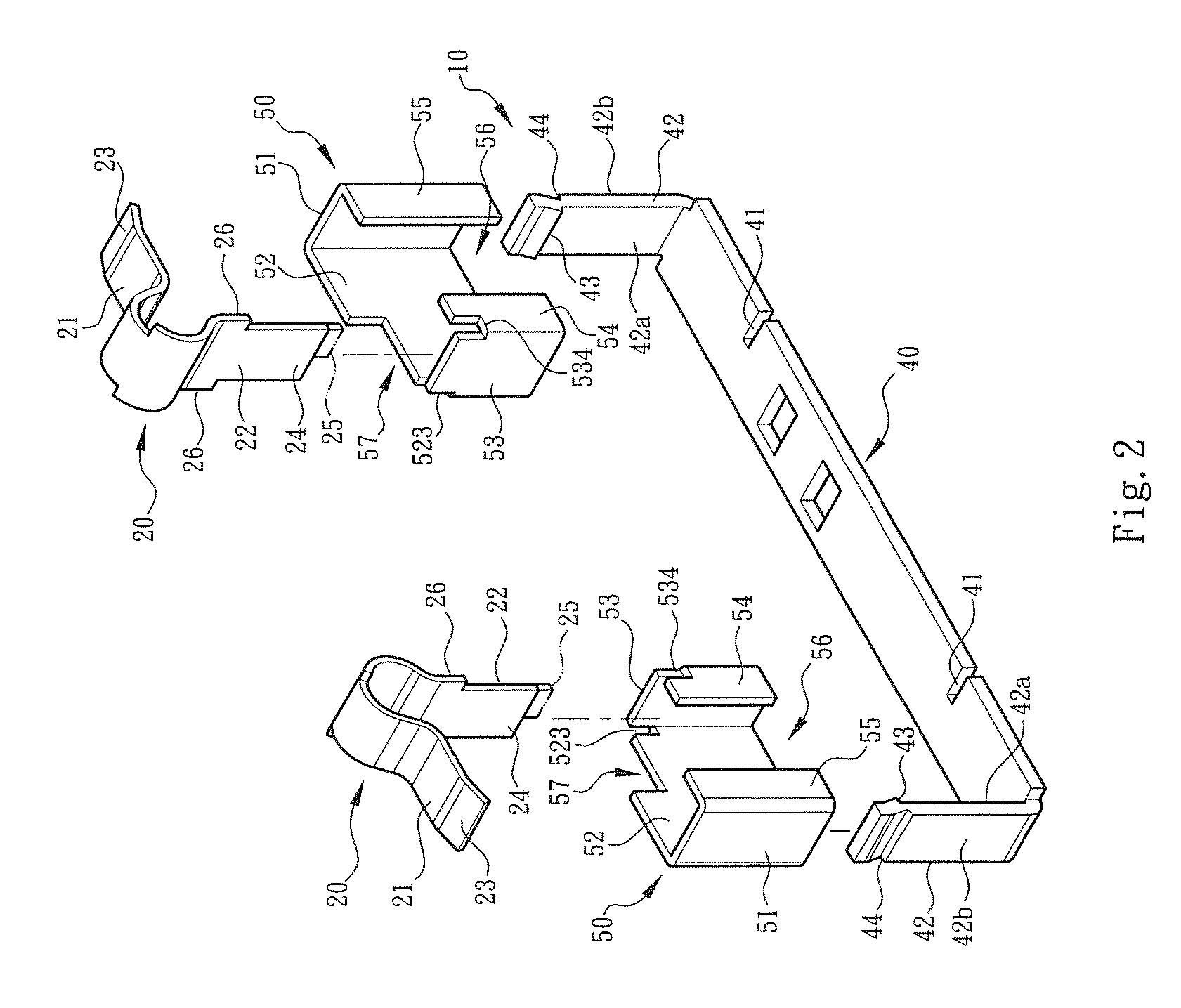
[0032]Please refer to FIGS. 1, 2 and 3. The conductive wire connection structure of rail-type electrical terminal of the present invention includes an assembly of a conductive support 10 and a metal leaf spring 20. The conductive support 10 and the metal leaf spring 20 are together mounted in an insulation case 30 for pivotally connecting with conductive wire and latching on a grounding rail (or conductive rail) to set up a common grounding device (not shown) for an electrical appliance or mechanical apparatus.

[0033]In a preferred embodiment, the conductive support 10 is divided into two parts, that is, a support main body 40 and a wire connector 50. The support main body 40 is selectively made of copper material with good electrical conductivity. The support main body 40 is formed with a notch 41 for assembling with the metal leaf spring 20. An arm section 42 perpendicularly extends from each of two ends of the support main body 40, whereby the support main body 40 has a U-shaped c...


PUM


Abstract

A conductive wire connection structure of rail-type electrical terminal is able to reduce the yield of waste material in manufacturing, enhance heat dissipation effect and increase operational and motional stability in condition of structural simplification. The conductive wire connection structure includes a conductive support mounted in an insulation case. The conductive support is divided into two parts of a U-shaped support main body and a C-shaped wire connector. The wire connector is assembled with a metal leaf spring and disposed on the support main body together with the metal leaf spring for pivotally connecting with the grounding conductive wire coming from an apparatus. The wire connector and the metal leaf spring are respectively formed with insertion sections for assembling the wire connector with the metal leaf spring to help the support main body to hold the metal leaf spring and prevent the metal leaf spring from deflecting.

Description

BACKGROUND OF THE INVENTION[0001]1. Field of the Invention[0002]The present invention relates generally to a conductive wire connection structure of rail-type electrical terminal, and more particularly to a conductive wire connection structure including a conductive support and a metal leaf spring. The conductive support is divided into two parts of a support main body and a wire connector. The support main body and the wire connector are respectively formed with specific configurations to reduce the yield of waste material in manufacturing. In addition, in condition of higher rigidity, the wire connector is assembled with the metal leaf spring to help in fixing the metal leaf spring and restricting the motional path of the metal leaf spring.[0003]2. Description of the Related Art[0004]A conventional electrical connection terminal includes a metal member or metal leaf spring enclosed in an insulation case (generally made of plastic material). When a conductive wire is inserted into ...

Claims


Application Information

Patent Timeline
Patent Type & Authority Patents(United States)
IPC IPC(8): H01R4/24H01R4/48H01R9/26
CPCH01R4/4818H01R4/4827H01R9/2675H01R4/48275H01R4/48185
Inventor WU, CHIH-YUANWU, CHIN-JUNG
Owner SWITCHLAB
Why Eureka
Try Eureka