Energizing system and method

a technology of energizing system and energizing system, applied in the direction of flexible ac transmission, electrical apparatus, arrangements responsive to excess voltage, etc., can solve the problems of increased overvoltage or reflection, affecting the design of power transmission system, and reducing the efficiency of the system, so as to improve the start-up of the system for transmitting electric power.

Active Publication Date: 2016-12-27
SIEMENS ENERGY AS
View PDF6 Cites 2 Cited by
  • Summary
  • Abstract
  • Description
  • Claims
  • Application Information

AI Technical Summary

Benefits of technology

[0008]The present embodiments may obviate one or more of the drawbacks or limitations in the

Problems solved by technology

When such electric power transmission cable is connected to a voltage source, the impedance of the cable may cause reflections and over-voltages within the cable or in equipment connected to the far end of the cable (e.g., in subsea devices).
In some installations, a transformer may be connected to the far end of the cable, which may result in increased over-voltages or reflections, and which may cause an even b

Method used


Image

  • Energizing system and method
  • Energizing system and method
  • Energizing system and method

Examples


Embodiment Construction

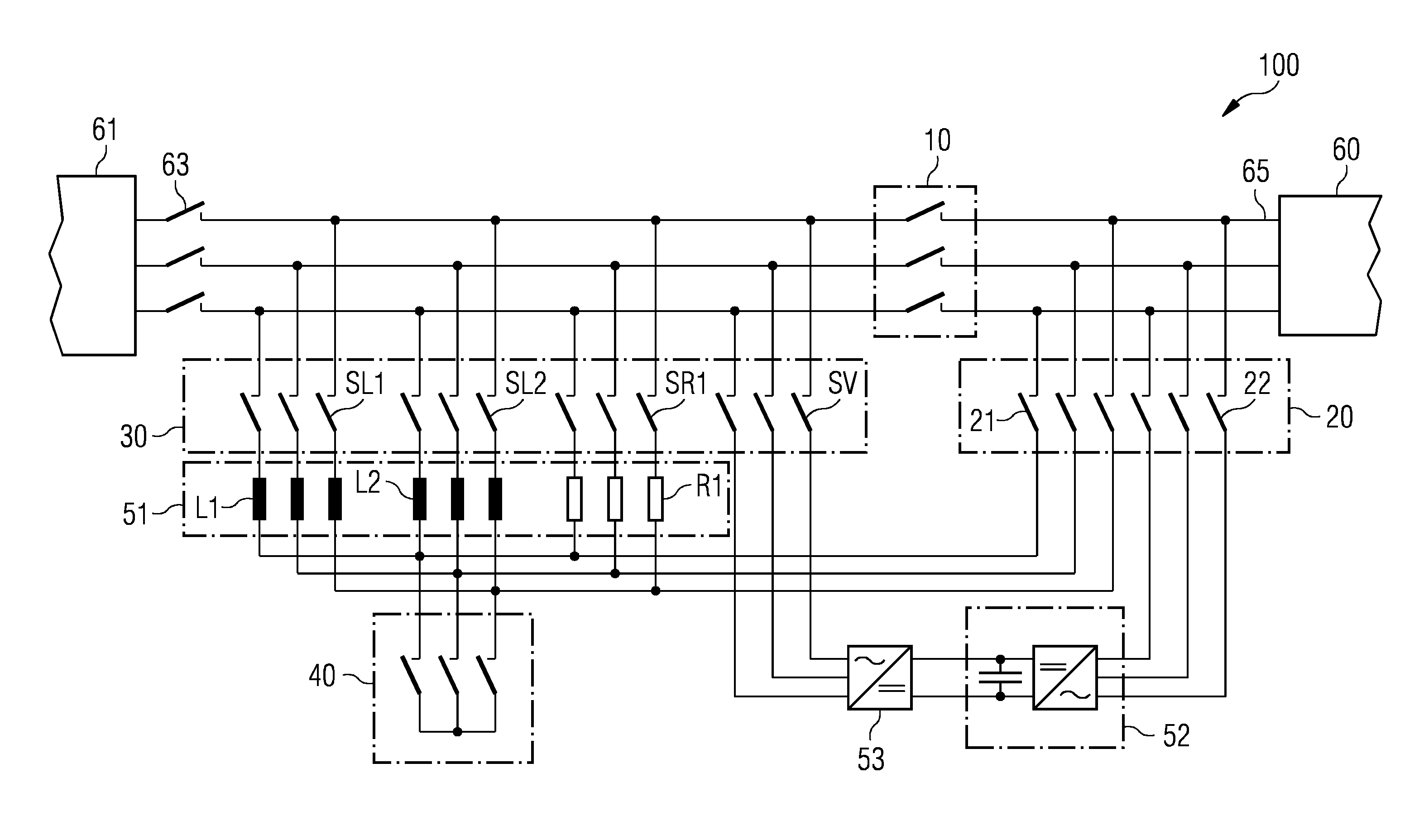
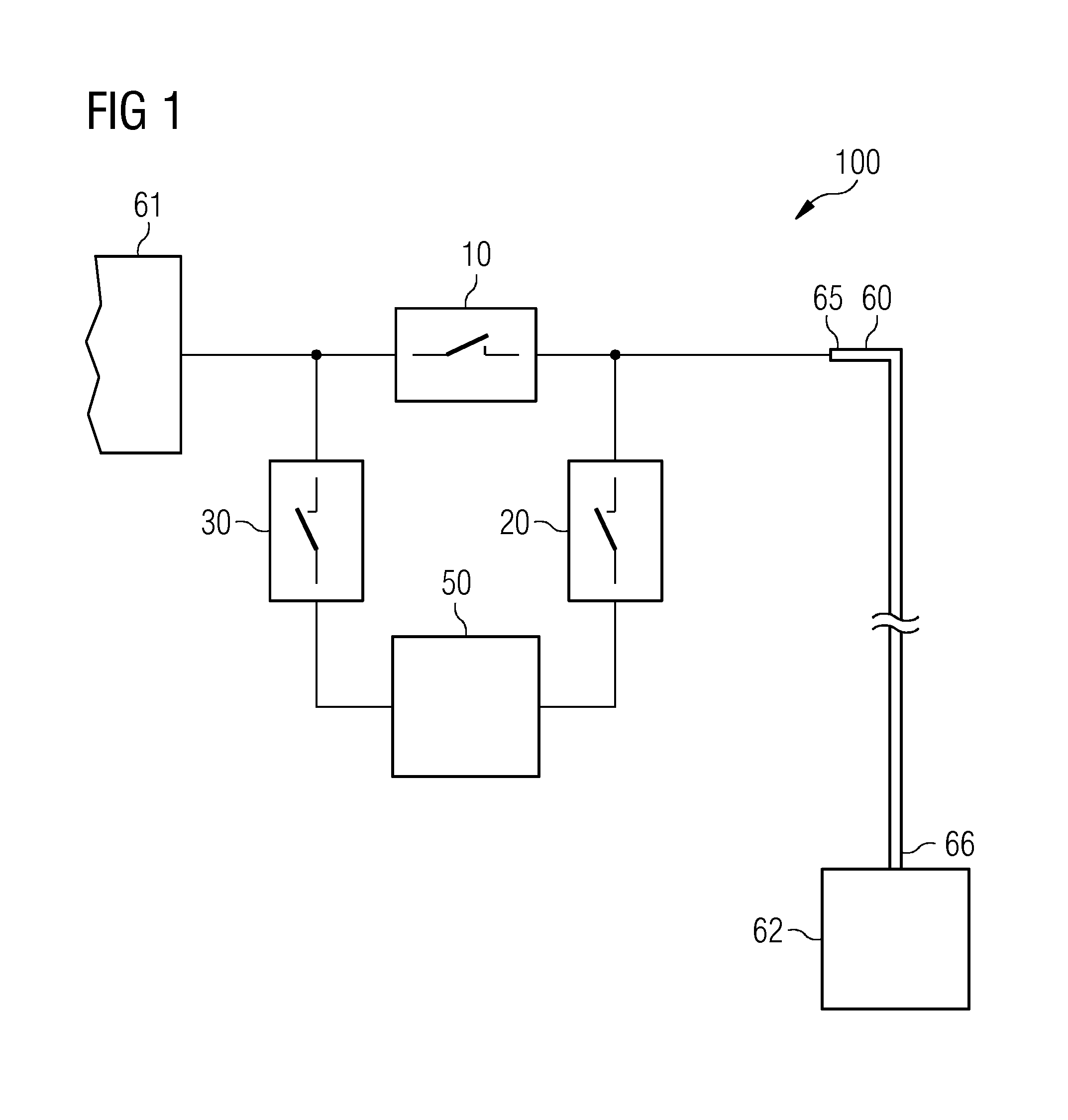
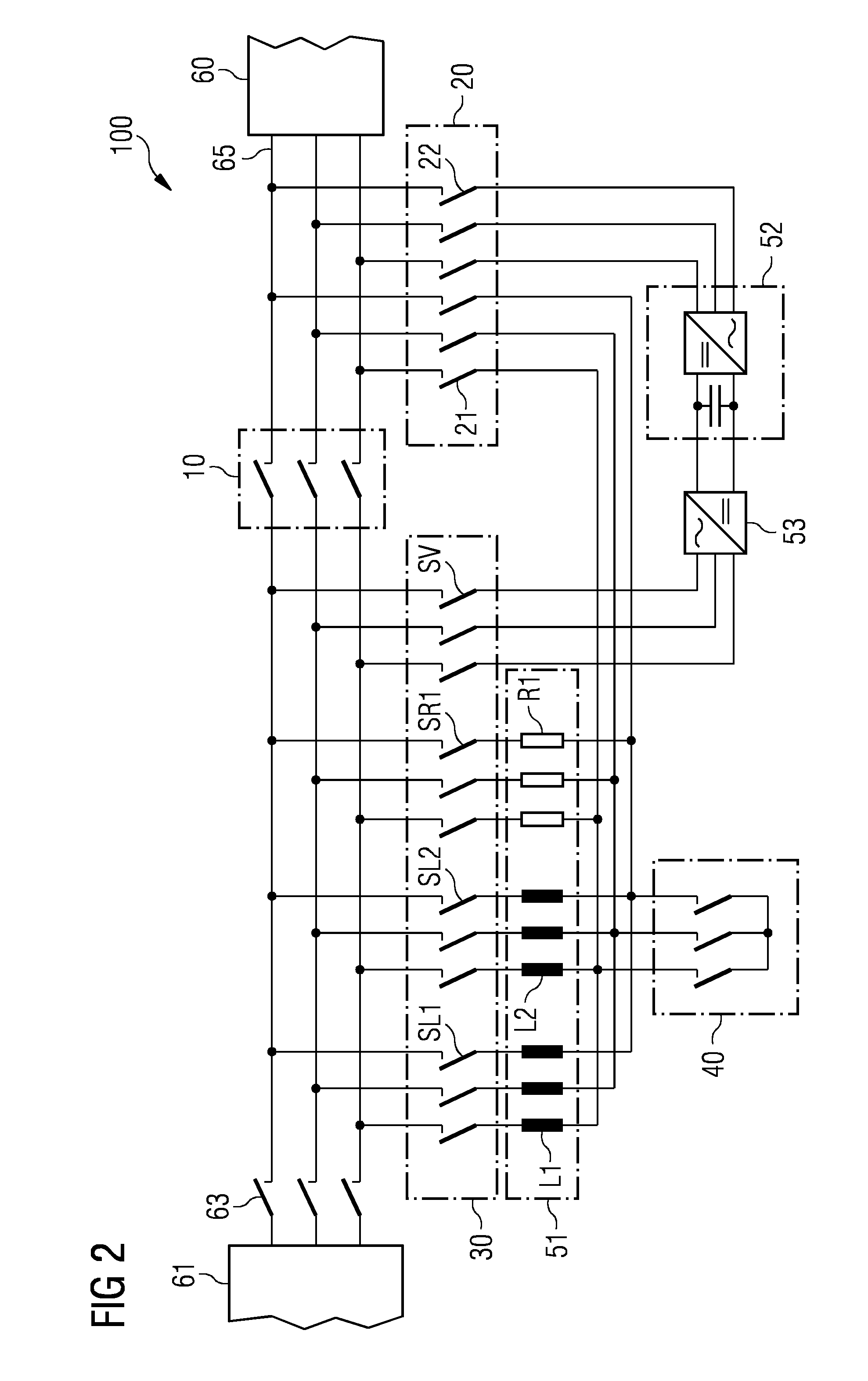
[0038]In the following, the embodiments illustrated in the accompanying drawings are described in more detail. The following description is only illustrative and non-restrictive. The drawings are only schematic representations, and elements in the drawings are not necessarily to scale with each other.

[0039]The coupling of physical or functional units as shown in the drawings and described hereinafter does not need to be a direct connection or coupling, but may also be an indirect connectional or coupling (e.g., a connection or a coupling with one or more additional intervening elements, such as fuses, circuit breakers, transformers or the like). A skilled person will understand that the physical or functional units illustrated and described herein with respect to the different embodiments do not need to be implemented as physically separate units. One or more physical or functional blocks or units may be implemented in a common circuit, chip, circuit element or unit, while other phy...


PUM


Abstract

An energizing system for energizing an electric power transmission cable (60) is provided. The electric power transmission cable (60) has an input side (65) coupled to an electric power source (61) and an output side (66) coupled to a load (621). The energizing system includes a first switch (10) connected between the power source (61) and the input side (65) of the power transmission cable (60) to connect and disconnect the power source (61) from the power transmission cable (60). A reactive power compensation unit (50) is further provided for compensating reactive power generated by at least one of the power transmission cable (60) or the load (62). A second switch and a third switch are provided for connecting the reactive power compensation unit (50) in parallel to the first switch (10) or the load (62).

Description

[0001]The present patent document is a §371 nationalization of PCT Application Serial Number PCT / EP2013 / 070558, filed Oct. 2, 2013, designating the United States, which is hereby incorporated by reference. This patent document also claims the benefit of EP 12187438.2, filed Oct. 5, 2012, which is also hereby incorporated by reference.FIELD[0002]The present embodiments relate to an energizing system for energizing an electric power transmission cable and to an energizing method.BACKGROUND[0003]Due to the increasing energy demands, offshore oil and gas production is moving into deeper waters. For providing an efficient and secure production, processing facilities are being installed at the ocean floor. Such subsea installations may include a range of components, including pumps, compressors, and the like as well as a power grid for operating the components. The power grid may, for example, include a subsea transformer, subsea switchgear, and subsea variable speed drives. The component...

Claims


Application Information

Patent Timeline
IPC IPC(8): H02H3/00H02H3/20H02J3/18
CPCH02H3/20H02H3/003H02J3/18Y02E40/12Y02E40/30Y02E40/10
Inventor BOE, OVE
Owner SIEMENS ENERGY AS
Why Eureka
Try Eureka