Power supply noise reduction circuit and power supply noise reduction method

a technology of power supply and noise reduction circuit, which is applied in the direction of gas-filled discharge tubes, solid cathodes, and efficient power electronics conversion, can solve the problems of difficult accurate testing, and achieve the effects of reducing noise, increasing testing time, and increasing the size of part shapes

Active Publication Date: 2017-01-03
ADVANTEST CORP
View PDF10 Cites 0 Cited by
  • Summary
  • Abstract
  • Description
  • Claims
  • Application Information

AI Technical Summary

Benefits of technology

[0019]According to the invention of claim 1, the first voltage is driven through the unity gain amplifier, so that noise can be reduced without causing any voltage drop in the power supply voltage and that the voltage supplied from the power supply can be supplied to the load as it is. Therefore, the power supply noise reduction circuit can be applied also to a case where an intended power supply voltage is to be supplied to the load by using a power supply that can program a constant voltage output, for example. Because there is no need to use a large-capacity capacitor or a coil with a high inductance, adverse effects (such as increase in the size of part shapes of the power supply noise reduction circuit, increase in the testing time due to an increased time constant, and need for design measures against easier occurrence of oscillation or increase in the amount of current oscillation in a transition duration) due to usage of a large-capacity capacitor, a high-inductance coil, or a resistor with a high resistance or a high allowable loss in the conventional techniques can be eliminated.
[0020]According to the invention of claim 2, the low-pass filter includes the second resistor and the capacitor that are coupled in series. Therefore, the low-pass filter can be easily configured.
[0021]According to the invention of claim 3, the filter switching unit bypasses the second resistor, so that activation and stoppage of the power supply noise reduction circuit can be quickly and easily switched. Therefore, the power supply noise reduction circuit can be activated at an arbitrary time when power supply with low noise is required and the power supply noise reduction circuit can be stopped at an arbitrary time when power supply is not required.
[0022]According to the invention of claim 4, the third resistor that decreases the input voltage to the unity gain amplifier through voltage division with the second resistor is provided. Therefore, the constant voltage output of the power supply noise reduction circuit is slightly lower than the constant voltage output of the power supply, and thus supply of power from the unity gain amplifier to the load, is prevented. Accordingly, there is substantially no power load on the unity gain amplifier and it suffices to supply power for absorbing noise power.
[0023]According to the invention of claim 5, the output line of the unity gain amplifier is switched off by the amplifier switching unit at a rise time or a fall time of the constant-voltage power supply. Therefore, current occurrence due to a difference between the voltage of the constant-voltage power supply and the output voltage of the unity gain amplifier can be prevented.
[0024]According to the invention of claim 6, the second resistor is bypassed before the power supply is turned on and the second resistor is connected after the power supply is turned on and the capacitor is promptly charged. Therefore, the power supply noise reduction circuit enables completion of activation substantially simultaneously with power-on and thus the power supply noise reduction circuit can be activated at an arbitrary time when power supply with low noise is required and can be stopped at an arbitrary time when power supply is not required.

Problems solved by technology

When noise (noise components) is included in a constant voltage output from the power supply, it is difficult to accurately conduct the test.

Method used


Image

  • Power supply noise reduction circuit and power supply noise reduction method
  • Power supply noise reduction circuit and power supply noise reduction method
  • Power supply noise reduction circuit and power supply noise reduction method

Examples


Embodiment Construction

[0029]An embodiment of the present invention is explained below in detail with reference to the accompanying drawings First, the basic concept of the embodiment is explained as [I], then specific contents of the embodiment are explained as [II], and lastly a modification of the embodiment is explained as [III]. The present invention is not limited to the embodiment.

[I] Basic Concept of the Embodiment

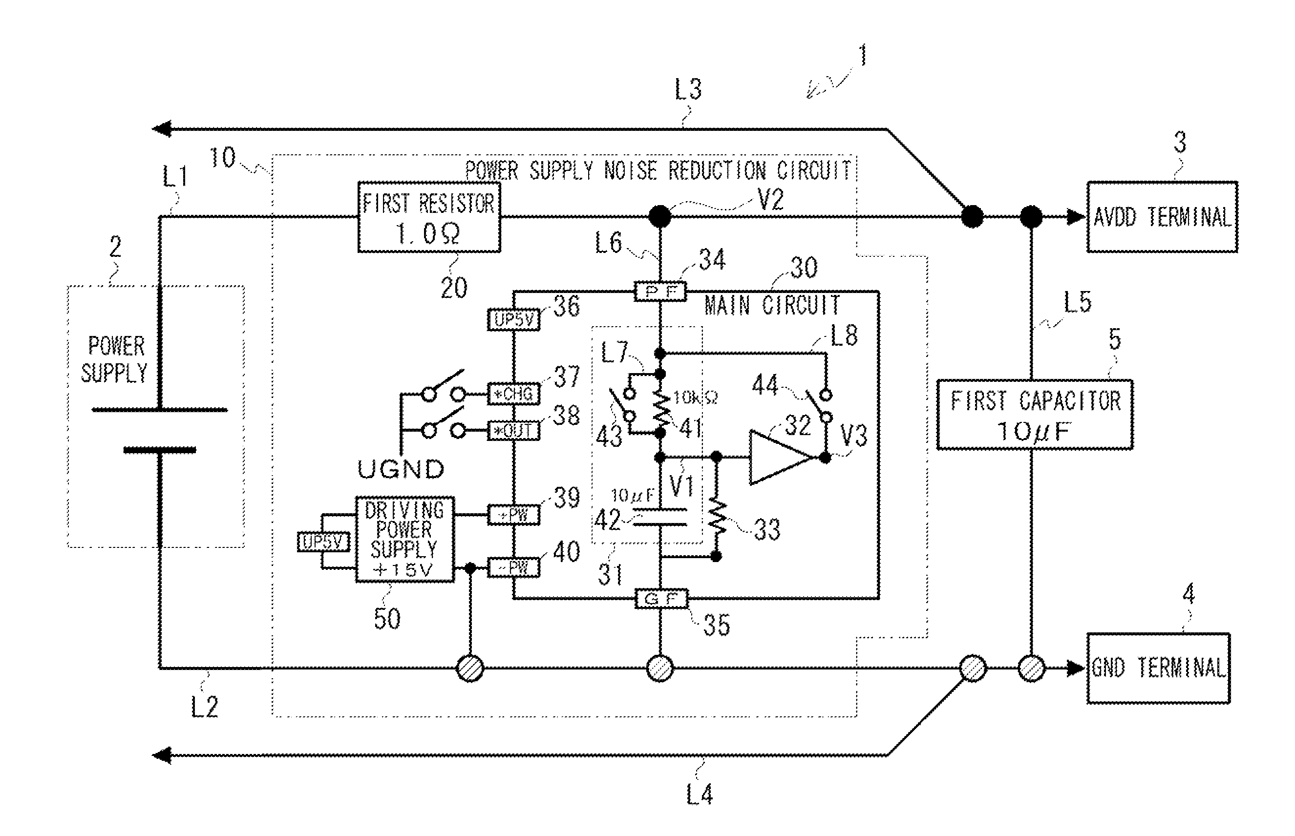
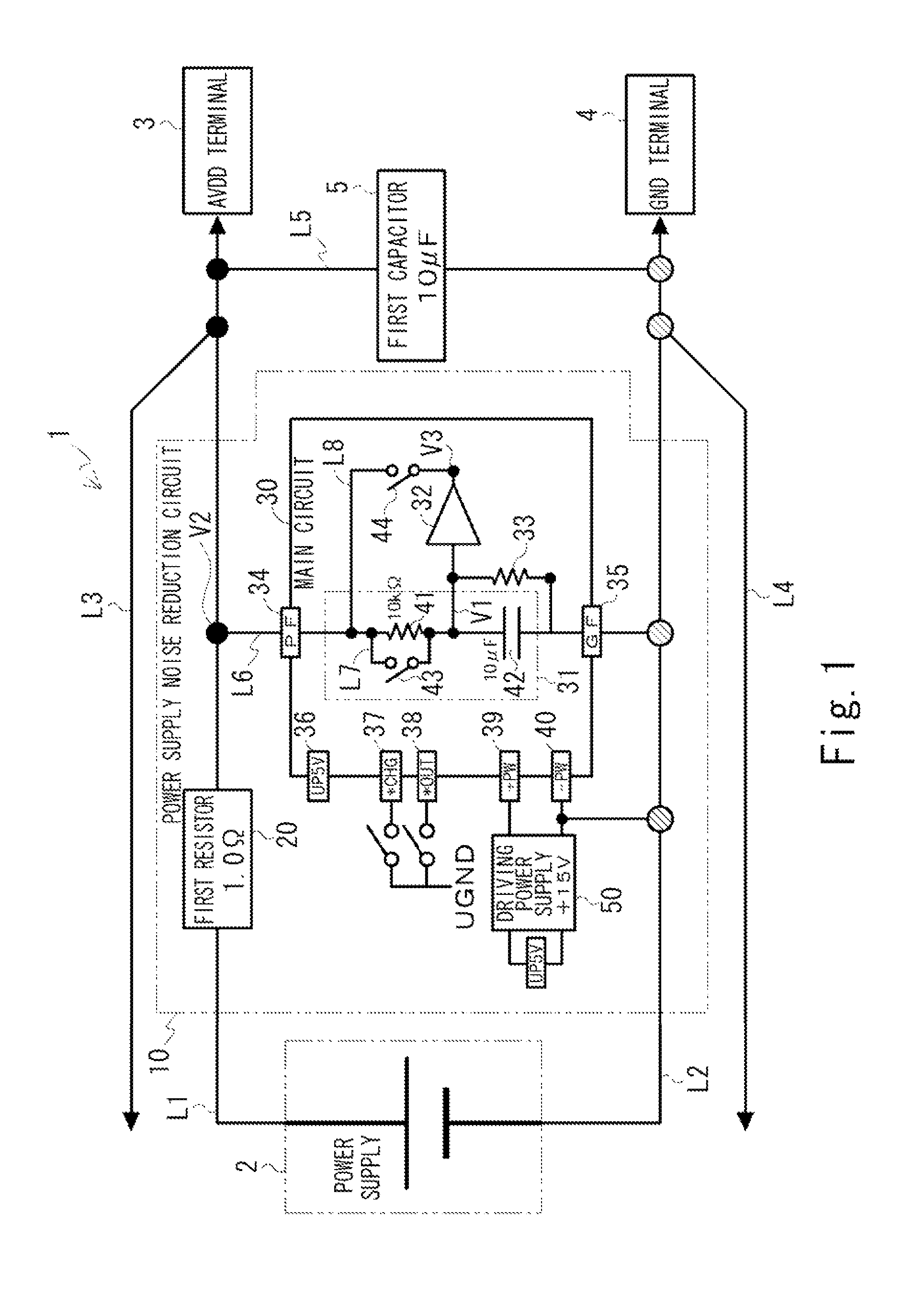
[0030]The basic concept of the present embodiment is explained first. A power supply noise reduction circuit and a power supply noise reduction method according to the present embodiment are for reducing noise included in a constant voltage output that is output from a power supply to a load. The power supply noise reduction circuit includes one that is configured independently from various devices and circuits such as a constant-voltage power supply device, and one that is incorporated in these devices and circuits. The latter corresponds to, for example, a case in which the power suppl...


PUM


Abstract

To provide a power supply noise reduction circuit and a power supply noise reduction method that do not require circuit elements to be increased in size and do not cause voltage drop in a power supply voltage. A power supply noise reduction circuit 10 that reduces noise included in a constant voltage output that is output from a power supply 2 to a load includes a first resistor 20 that is inserted into a power supply line L1 extending from the power supply 2 to the load, a filter 31 that is coupled to a load terminal of the first resistor 20 and outputs a first voltage that is obtained by reducing the noise from the constant voltage output, and a unity gain amplifier 32 that drives the first voltage output from the filter 31 and outputs the driven first voltage to the load terminal of the first resistor 20.

Description

TECHNICAL FIELD[0001]The present invention relates to a power supply noise reduction circuit and a power supply noise reduction method for reducing noise included in a constant voltage output that is output from a power supply to a load.BACKGROUND ART[0002]When a semiconductor device is tested by a semiconductor tester, the test is conducted by driving the semiconductor device with electric power from a power supply. When noise (noise components) is included in a constant voltage output from the power supply, it is difficult to accurately conduct the test. Accordingly, power supply noise reduction circuits for reducing noise included in a constant voltage output that is output from a power supply to a semiconductor device have been conventionally used in practice. These power supply noise reduction circuits are broadly divided into a passive low-pass filter that is formed only by passive components and an active low-pass filter that uses active components.[0003]A passive filter is g...

Claims


Application Information

Patent Timeline
Patent Type & Authority Patents(United States)
IPC IPC(8): H02M1/14
CPCH02M1/14H02M1/143B60W2050/0056H01J17/005H02M3/157Y02B70/10
Inventor SATO, TOSHIYUKI
Owner ADVANTEST CORP
Why Eureka
Try Eureka