Surface acoustic wave resonator, surface acoustic wave oscillator, and electronic apparatus

a surface acoustic wave and oscillator technology, applied in the direction of oscillation generators, impedence networks, electrical apparatus, etc., can solve the problems of deterioration of characteristics, low reflection efficiency of saws using grating reflectors, and inability to easily implement miniaturized saw devices with high q values, etc., to achieve high reliability

Active Publication Date: 2017-01-03
SEIKO EPSON CORP
View PDF156 Cites 7 Cited by
  • Summary
  • Abstract
  • Description
  • Claims
  • Application Information

AI Technical Summary

Benefits of technology

The patent text is that it describes how to create an electronic device that is highly reliable. This means that we can get a device that is consistent and stable over a long period of time. This is important because it helps to ensure that the device works well and is dependable.

Problems solved by technology

Therefore, the reflection efficiency of the SAW using a grating reflector is lower than that of an ST-cut quartz crystal SAW propagating along the surface of the piezoelectric substrate, and there is a problem in that a miniaturized SAW device having a high Q value cannot be easily implemented.
However, the applicants of this application has found through experiments that, when the film thickness of the electrode is formed to be large, environment-resistant characteristics such as characteristics that change by time or temperature-resistant shock characteristics deteriorate.
In addition, in a case where the main purpose is to improve the frequency-temperature characteristics, the film thickness of the electrode needs to be large as described above, and it is difficult to avoid the deterioration of the characteristics changing by time and the temperature-resistant shock characteristics that is accompanied with the large film thickness.
This can be also applied to the Q value, and it is difficult to realize a high Q value without forming the film thickness of the electrode to be large.

Method used


Image

  • Surface acoustic wave resonator, surface acoustic wave oscillator, and electronic apparatus
  • Surface acoustic wave resonator, surface acoustic wave oscillator, and electronic apparatus
  • Surface acoustic wave resonator, surface acoustic wave oscillator, and electronic apparatus

Examples


first embodiment

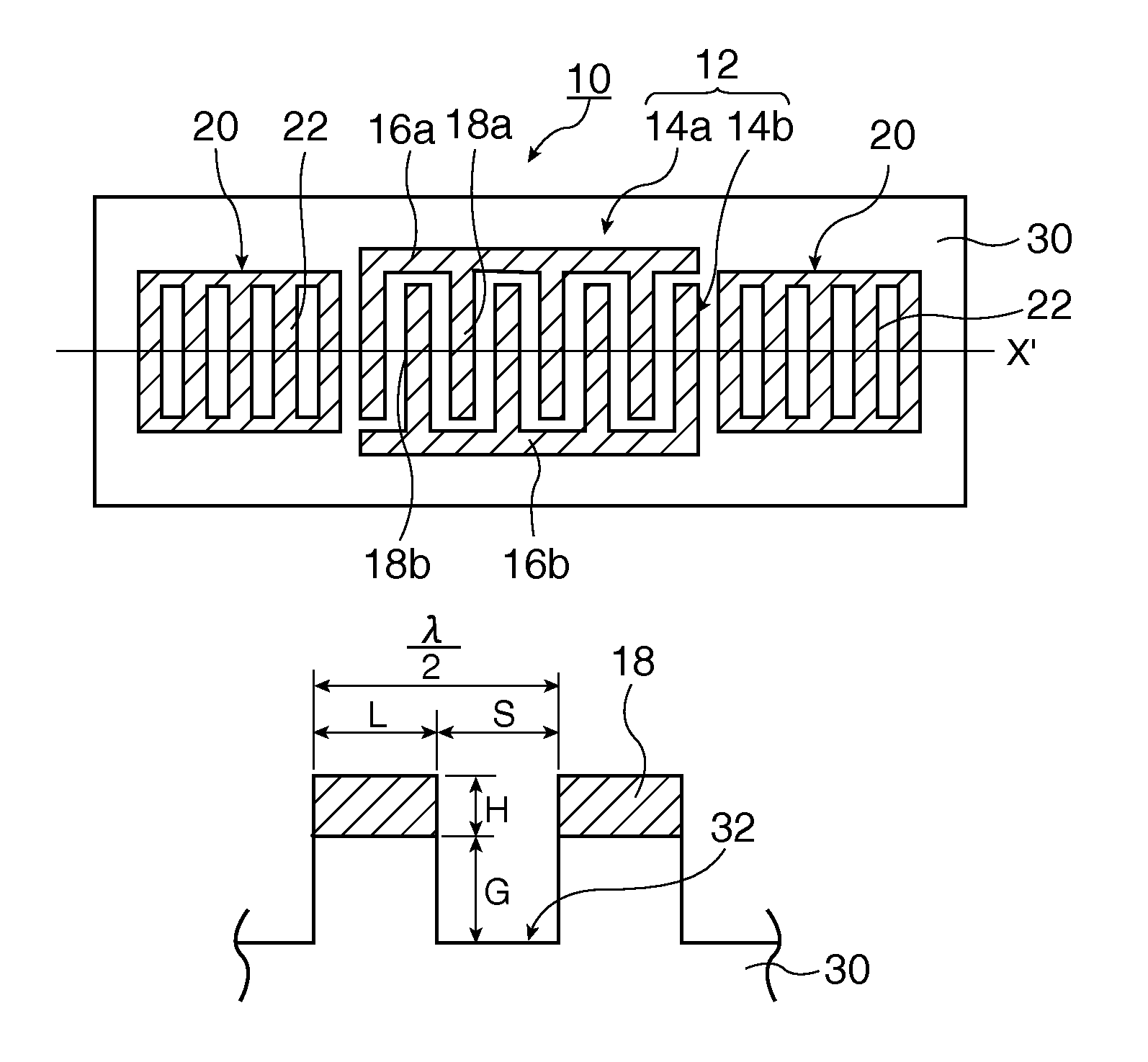
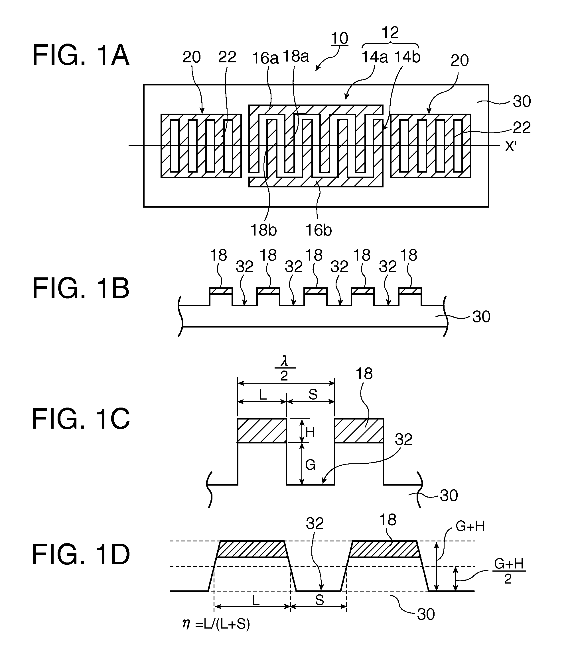
[0130]First a surface acoustic wave (SAW) resonator according to a first embodiment of the invention will be described with reference to FIGS. 1A to 1D. Of FIGS. 1A to 1D, FIG. 1A is a plan view of the SAW resonator, FIG. 1B is a partially enlarged sectional view, FIG. 1C is a partially enlarged view of FIG. 1B for illustrating details thereof, and FIG. 1D is a partially enlarged view of FIG. 1C, is a sectional shape that can be assumed in a case where a SAW resonator according to an embodiment of the invention is manufactured using a photolithography technique and an etching technique, and is a diagram illustrating a method of specifying a line occupancy ratio η of IDT electrode fingers in a case where the cross-sectional shape is not a rectangle but a trapezoid. It is appropriate that the line occupancy ratio η is the ratio of the width L of a convex portion to a value (L+S) acquired by adding the width L of the convex portion and a width S of a groove 32 at a height of ½ of a val...

second embodiment

[0330]Next, a surface acoustic wave resonator according to a second embodiment of the invention will be described.

[0331]FIG. 62 is a diagram showing a SAW device according to the second embodiment of the invention and is a diagram representing a partially enlarged cross-section.

[0332]Hereinafter, the second embodiment will be described, and a difference between the first and second embodiments will be focused, and the description of similar configurations will be omitted.

[0333]The SAW resonator 10 shown in FIG. 62 is similar to the SAW resonator 10 shown in FIG. 59 except that the conductive strip of the reflector (reflection unit) 20 is omitted. In other words, the reflector 20 of the SAW resonator 10 shown in FIG. 62 is configured by a plurality of grooves 322 that are formed by depressing the surface of a quartz crystal substrate 30. According to this embodiment, since the formation of the conductive strip in the reflector 20 is omitted, the manufacturing of the reflector 20 can ...

third embodiment

[0341]Next, a surface acoustic wave resonator according to a third embodiment of the invention will be described.

[0342]FIG. 64 is a diagram showing a SAW device according to the third embodiment of the invention and is a diagram representing a partially enlarged cross-section.

[0343]Hereinafter, the third embodiment will be described, and a difference between the first and third embodiments will be focused, and the description of similar configurations will be omitted.

[0344]The SAW resonator 10 shown in FIG. 64 is similar to the SAW resonator 10 shown in FIG. 59 except that the groove arranged between the conductive strips 22 of the reflector (reflection unit) 20 is omitted. In other words, the reflector 20 of the SAW resonator 10 shown in FIG. 64 is configured by a plurality of conductive strips 22 formed on the quartz crystal substrate 30. According to this embodiment, since the formation of the groove in the reflector 20 is omitted, the manufacturing of the reflector 20 can be eas...


PUM


Abstract

A surface acoustic wave resonator includes an IDT that is disposed on a quartz crystal substrate of Euler angles (−1.5°≦φ≦1.5°, 117°≦θ≦142°, ψ) and excites a surface acoustic wave resonant in an upper part of a stop-band of the IDT, and inter-electrode finger grooves that are acquired by depressing the substrate located between electrode fingers configuring the IDT. The wavelength of the surface acoustic wave, the depth of the inter-electrode finger grooves, the line occupancy ratio of the IDT, and the film thickness of the electrode fingers of the IDT are set in correspondence with one another.

Description

CROSS-REFERENCE TO RELATED APPLICATIONS[0001]This is a continuation patent application of U.S. application Ser. No. 13 / 162,162 filed Jun. 16, 2011, now U.S. Pat. No. 9,088,263 issued Jul. 21, 2015, which claims priority to Japanese Patent Application No. 2010-138495, filed Jun. 17, 2010, all of which are expressly incorporated by reference herein in their entireties.BACKGROUND[0002]1. Technical Field[0003]The present invention relates to a surface acoustic wave resonator and a surface acoustic wave oscillator in which the surface acoustic wave resonator is mounted, and more particularly, to a type of surface acoustic wave resonator in which grooves are arranged in a substrate surface and a surface acoustic wave oscillator and an electronic apparatus in which such a type of surface acoustic wave resonator is mounted.[0004]2. Related Art[0005]In a surface acoustic wave (SAW) device (for example, a SAW resonator), the influence of the stop band of a SAW, a cut angle of a piezoelectric ...

Claims


Application Information

Patent Timeline
Patent Type & Authority Patents(United States)
IPC IPC(8): H03H9/25H03H9/64H03H9/02H03B5/32H03H9/125H03H9/00
CPCH03H9/02551H03B5/326H03H9/02653H03H9/02661H03H9/02669H03H9/02677H03H9/64H03H2009/0019H03B5/30H03H9/25
Inventor YAMANAKA, KUNIHITO
Owner SEIKO EPSON CORP
Why Eureka
Try Eureka