Air flow limiter with closed/open sensing

a technology of air flow limiter and closed/open sensing, which is applied in the field of plastic article manufacturing, can solve the problems of resin loading, vacuum dropping too much, damage to the material being conveyed, etc., and achieves the effect of facilitating the expansion of the pneumatic plastic resin pellet conveying system and reducing the cost of those systems

Active Publication Date: 2017-01-24
MAGUIRE STEPHEN B
View PDF127 Cites 14 Cited by
  • Summary
  • Abstract
  • Description
  • Claims
  • Application Information

AI Technical Summary

Benefits of technology

[0059]The instant invention provides an improvement to known pneumatic plastic resin pellet conveying systems, reducing the costs of those systems while providing consistent control of delivered cubic feet per minute of air. The invention also facilitates easy expansion of the pneumatic plastic resin pellet conveying system as the system grows. Such expandable systems are made feasible by an inventive air flow limiter embodying aspects of this invention.
[0060]In one aspect of this invention, air flow control devices, most desirably of the type newly disclosed herein and only slightly less desirably of the type disclosed in co-pending U.S. patent application Ser. No. 14 / 185,016 entitled “Air Flow Regulator”, filed 20 Feb. 2014 in the name of Stephen B. Maguire, are added to each receiver so that the air pulled from any single receiver at the correct predetermined, preselected flow rate. This prevents excessive flow rates and “open” lines that dump too much air into the system.

Problems solved by technology

However, a larger pump may draw too much air with resulting damage to the material being conveyed.
While a larger pump could load several receivers at once, there is a risk that an “open” line, namely a line pulling only air, and no resin material, would cause the vacuum to drop too much, and no resin would load.
Also, when only one receiver is loading resin, air velocity might be too high, again with a risk of damaging the resin.
With such an approach, the positive pressure results in a movement of substantial amounts of air which may be used to carry the plastic resin pellets.
Use of such high capacity vacuum pumps results in a big rush of below atmospheric pressure air through the line, carrying the plastic resin pellets over a long distance.
Of course, the higher the number of receivers served by the system, the higher the cost.
If air flow is too slow, the plastic resin pellets fall out of the air stream and lie on the bottom of the conduit, with resulting risk of clogging the conduit.
If air flow is too fast, the plastic resin pellets can skid along the conduit surface.
In such case, harder, more brittle plastic resin pellets may be damaged, resulting in dust within the conduit, which when drawn into the vacuum pump can damage the vacuum pump and render the system inoperative.
This results in “angel hair”—long, wispy-thin strands of plastic film which eventually clog the conduit and cause the system to shut down.
However, a single twenty horsepower blower would result in far too high a conveying speed for the plastic resin pellets through any reasonable size conduit.
Even with careful planning and design, results achieved by such pneumatic plastic resin pellet conveying systems are not consistent.

Method used


Image

  • Air flow limiter with closed/open sensing
  • Air flow limiter with closed/open sensing
  • Air flow limiter with closed/open sensing

Examples


Embodiment Construction

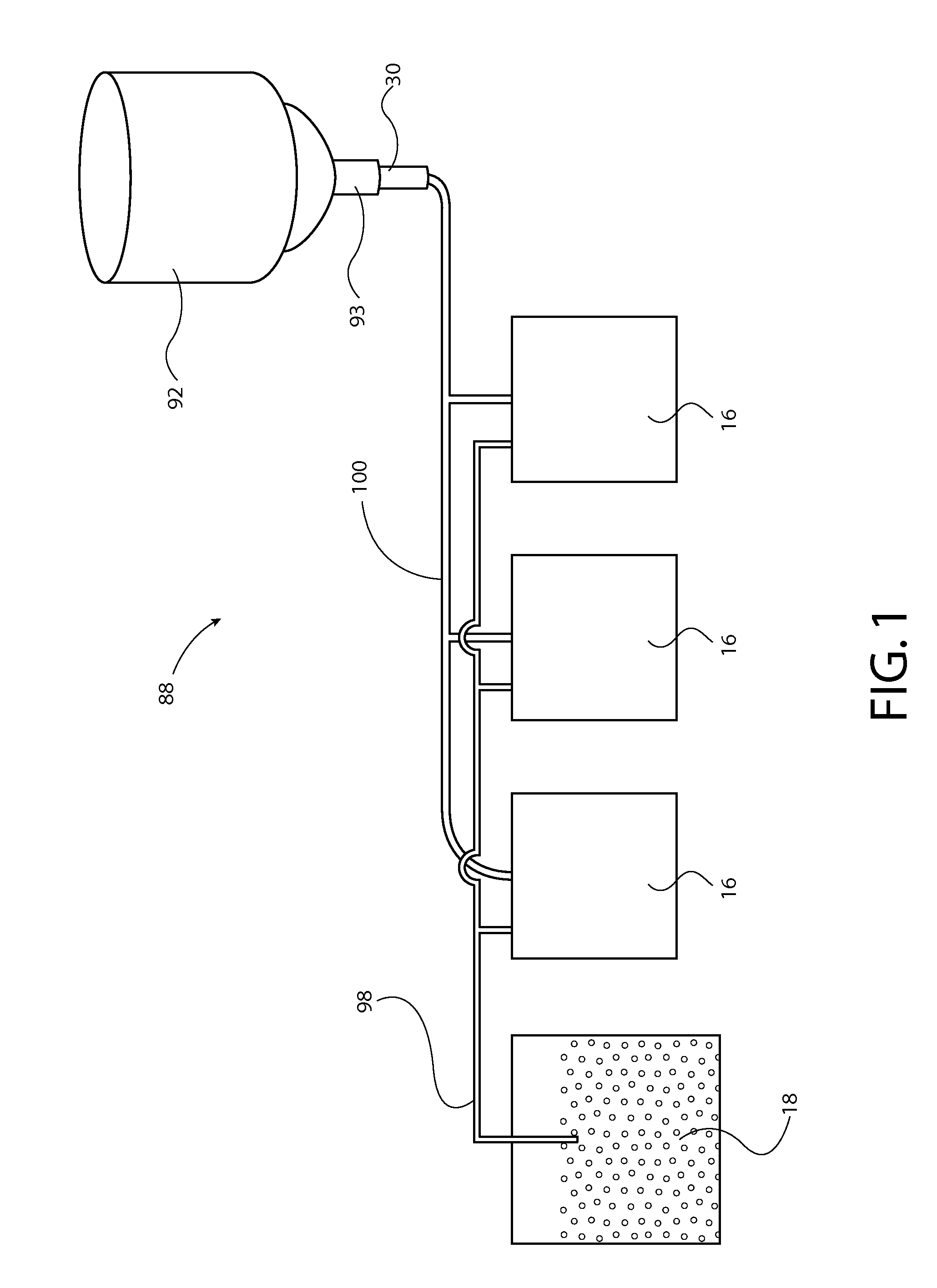
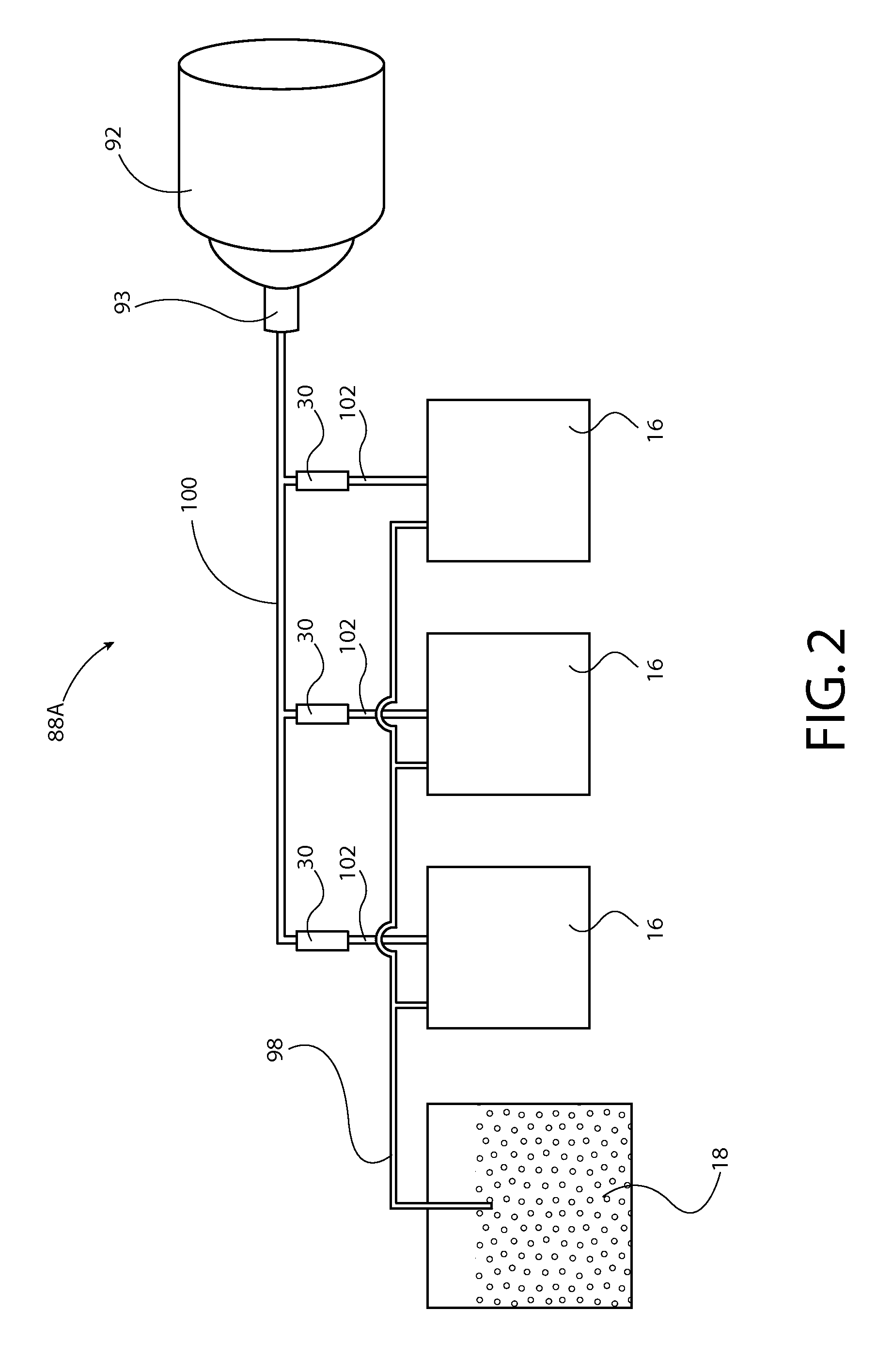
[0111]In this application, unless otherwise apparent from the context it is to be understood that the use of the term “vacuum” means “air at slightly below atmospheric pressure.” The “vacuum” (meaning air at slightly below atmospheric pressure) provides a suction effect that is used to draw granular plastic resin material out of a supply and to convey that granular plastic resin material through various conduits to receivers where the granular resin material can be temporarily stored before being molded or extruded. Hence, in this application it is useful for the reader mentally to equate the term “vacuum” with the term “suction”.

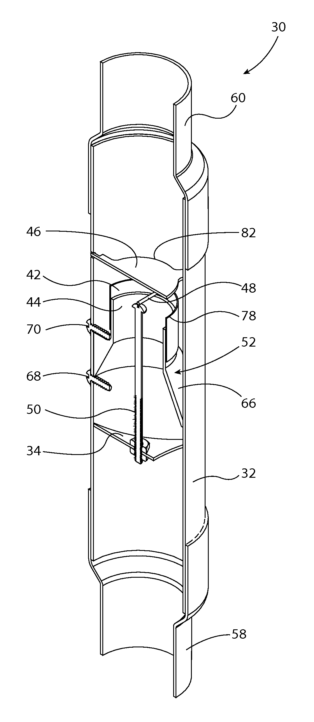
[0112]This invention is based on the flow limiter disclosed and claimed in pending U.S. patent application Ser. No. 14 / 185,016 referenced above and adds at least a sensor to detect when the limiter has stopped flow, or to detect other flow conditions, according to the location of the sensor.

[0113]When air flow is below the design limit, the limiter remains ...


PUM


Abstract

Method and apparatus for air flow regulation comprise a vertically oriented tube, a sail assembly positioned in the tube and moveable therewithin responsively to air flow through the tube to regulate rate of air flow through the tube and to stop air flow through the tube upon air flow rate through the tube exceeding a preselected value with a detector for sensing when the sail assembly has stopped air flow through the tube as a result of air flow rate exceeding said pre-selected value.

Description

CROSS-REFERENCE TO RELATED PATENT APPLICATIONS[0001]This patent application is a 35 USC 120 continuation-in-part of U.S. Ser. No. 14 / 185,016 entitled “Air Flow Regulator” filed 20 Feb. 2014 in the name of Stephen B. Maguire, and is also a 35 USC 120 continuation-in-part of U.S. Ser. No. 14 / 574,561 entitled “Resin Delivery System with Air Flow Regulator” filed 18 Dec. 2014 in the name of Stephen B. Maguire. Applicant claims the priority of both of these applications.TECHNOLOGICAL BACKGROUND[0002]This invention relates to manufacture of plastic articles and more particularly relates to pneumatic conveyance and processing of plastic resin pellets prior to molding or extrusion of those pellets into a finished or semi-finished plastic product.[0003]In this patent application, injection and compression molding presses and extruders are collectively referred to as “process machines.”[0004]The plastics industry is very diversified; there are thousands of different products, hundreds of mate...

Claims


Application Information

Patent Timeline
Patent Type & Authority Patents(United States)
IPC IPC(8): B65G53/66G05D7/01B65G53/58
CPCB65G53/66B65G53/58G05D7/0153Y10T137/0318Y10T137/8242
Inventor MAGUIRE, STEPHEN B.
Owner MAGUIRE STEPHEN B
Why Eureka
Try Eureka