Electrochemical system for storing electricity in metals

a metal and electrochemical technology, applied in the direction of electrochemical generators, fuel and primary cells, fuel and secondary cells, etc., can solve the problems of short service life of pumped hydropower, limited availability of suitable lands, and fast degradation of bi-functional air cathodes, etc., to achieve low cost storage and transport

a metal and electrochemical technology, applied in the direction of electrochemical generators, fuel and primary cells, fuel and secondary cells, etc., can solve the problems of short service life of pumped hydropower, limited availability of suitable lands, and fast degradation of bi-functional air cathodes, etc., to achieve low cost storage and transport

US9553328B2Active Publication Date: 2017-01-24E ZINC INC

Image

  • Electrochemical system for storing electricity in metals
  • Electrochemical system for storing electricity in metals
  • Electrochemical system for storing electricity in metals

Examples


Embodiment Construction

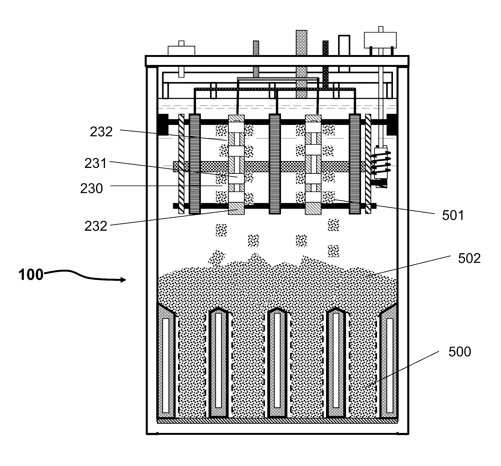
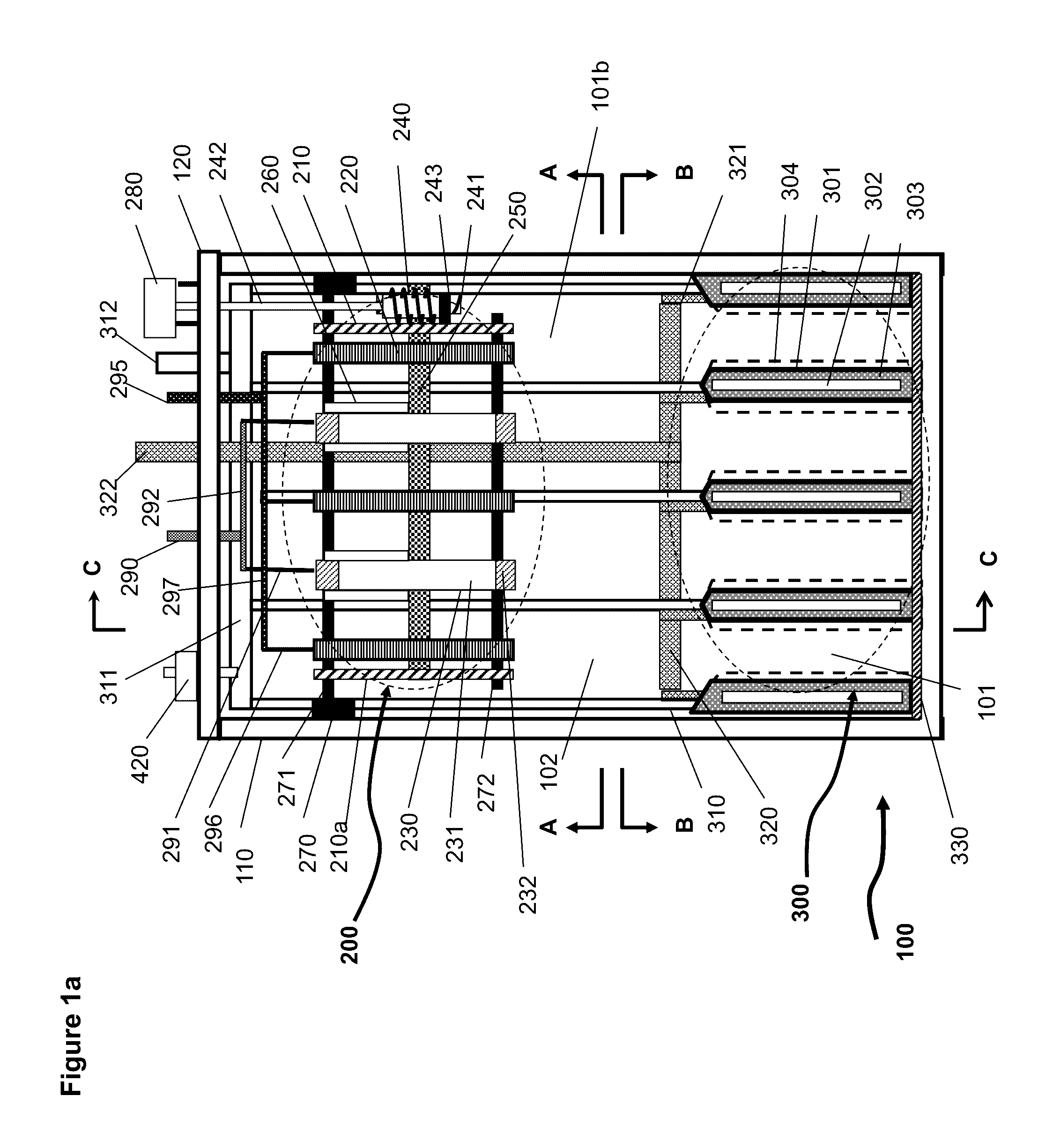
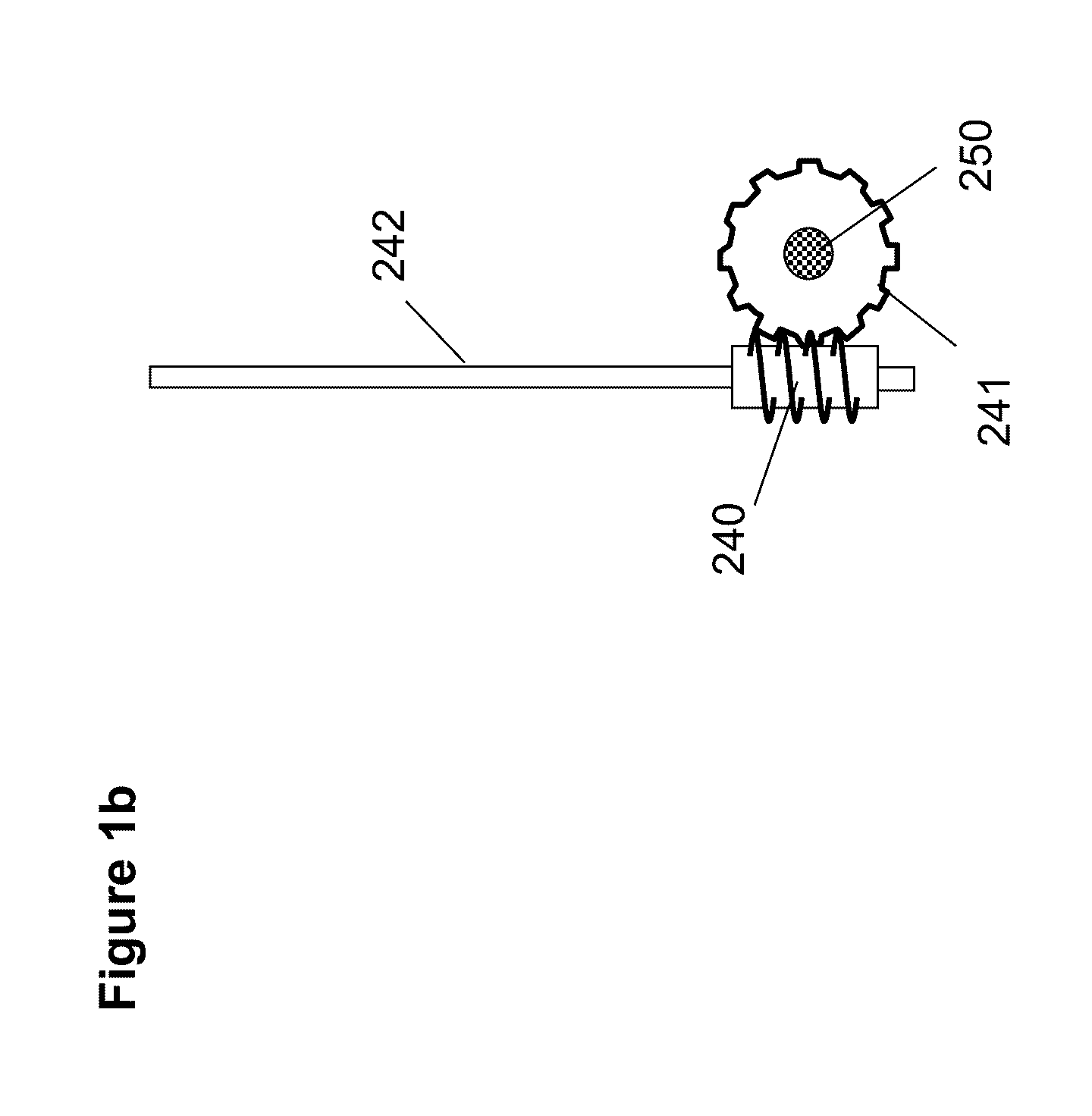
[0066]An exemplary embodiment of the electrochemical cell according to the principles of the present invention uses oxidation and reduction of oxygen in the air and of a metal as the electrochemical reaction couple, of which the basic elements and structure are illustrated in FIG. 1 et al to FIG. 5. FIG. 1a is a schematic illustration of the electrochemical cell without electrolyte and metal. FIG. 2a is a schematic illustration of the electrochemical cell shown in FIG. 1a having electrolyte and deposited metal materials. FIGS. 3a, 4 and 5 are the schematic illustrations viewed from different cross sectional planes and directions indicated in FIG. 1a.

[0067]As shown in FIGS. 1a and 2a the electrochemical cell 100 includes a charging assembly 200 (roughly outlined by the dashed line), a discharging assembly 300 (roughly outlined by the dashed line), an electrolyte 400, a container 110 and a number of auxiliary components which will be described in the following paragraphs.

[0068]The ch...


PUM

PropertyMeasurementUnit
widthaaaaaaaaaa
lengthaaaaaaaaaa
lengthaaaaaaaaaa

Abstract

An electrochemical system for storing electrical energy in metallic material comprises a charging assembly having one or more cathode and anode couples for metal deposition and a discharging assembly having one or more cathodes and spaces amid the cathodes for containing metal anode. The charging assembly and discharging assembly are physically separated allowing independent operation of the charging and discharging facilities and independent scaling of power and energy capabilities. It also allows storage of anode metal material in simple containers separated from the charging and discharging assemblies and thus allows for economical energy storage.

Description

CLAIM OF PRIORITY[0001]This application claims priority to U.S. provisional patent application Ser. No. 61 / 870,104, filed on Aug. 26, 2013.FIELD OF THE INVENTION[0002]This invention relates to electrochemical technologies for electrical energy storage and particularly relates to metal-air batteries, fuel cells and flow batteries.BACKGROUND OF THE INVENTION[0003]Electricity storage is an important enabling technology for effective use of renewable energy sources such solar and wind. There are two broad categories of electricity storage applications based on the duration of storage: short durations, from a fraction of second to about one hour, and long durations, from a few hours to ten or hundred of hours. The short duration types are typically used for power support to ensure the reliability and quality of electrical power for which there are technologies in the early stage of commercial application. Long duration types are needed for applications to separate the times between gener...

Claims


Application Information

Patent Timeline
24 Jan 2017
Publication
US9553328B2
IPC
H01M12/06; H01M12/08; H01M8/22; H01M8/18
CPC
H01M8/184; H01M8/22; H01M8/225; H01M12/08; Y02E60/528; Y02E60/50; Y02E60/10; H01M12/065
Inventors
ZHANG, XIAOGE GREGORY